


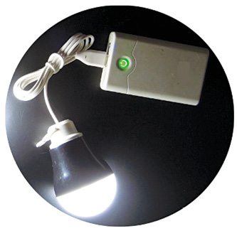
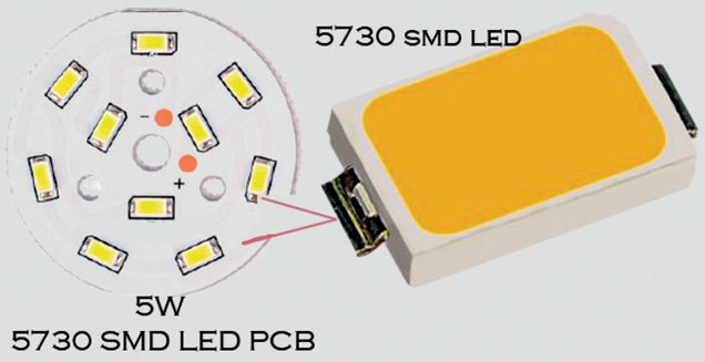
 A typical USB LED bulb shown in Fig. 1 is a 5V, 5W USB-powered solid-state lamp. At the heart of this light bulb is a circular aluminium PCB made with a bunch of 5730 SMD super-bright LEDs. Typical working voltage of a single 5730 SMD LED is in the range of 2.9V to 3.4V, and its current consumption is about 150mA. Fig. 2 shows some details of SMD LEDs used in the USB LED bulb. This gizmo inspired me to design a distinct USB LED night light with battery backup.
Circuit and working
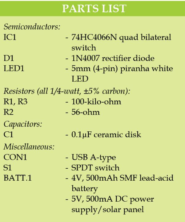
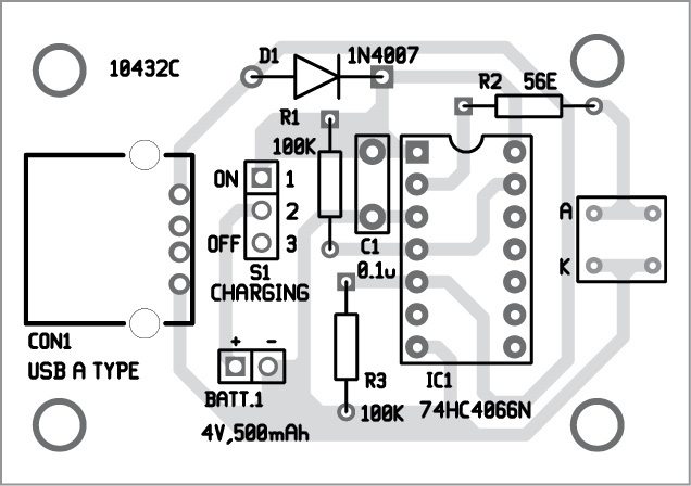
Circuit diagram of the USB LED night light is shown in Fig. 3. It is built around USB A-type connector (CON1), diode 1N4007 (D1), bilateral switch IC 74HC4066N (IC1) and 5mm piranha white LED (LED1).
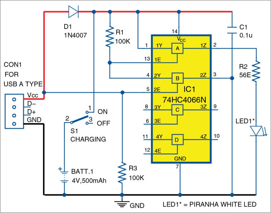
This circuit is wired around the popular quad bilateral switch 74HC4066N. Note that, only two of its switches (IC1A and IC1B) are used here. Front-end of the circuit is a standard USB (A) male connector.

During day time, DC voltage available from a standard USB port (or from a 5V solar panel) can be used to charge the rechargeable battery (BATT.1) of the circuit. The battery gets charged through diode D1 connected in series. Since IC1B is closed by the input voltage, IC1A remains in open state and LED1 rests in off condition.
However, if voltage supplied by the USB port/solar panel is not available, or if it drops to about 1.3V, voltage at the control input of IC1B drops to zero, causing the switch to open. Consequently, IC1A closes, connecting LED1 to the battery through resistor R2, which sets LED1 current to a safe value.
Intensity of LED1 may be adjusted by changing the value of R2, observing a maximum current of 20mA through IC1A. Switch S1 prevents the battery from being discharged if the circuit is not in use for some reason.
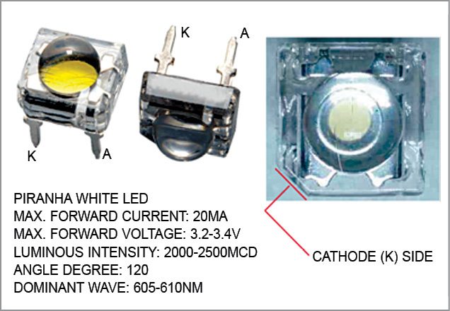
The 5mm (4-pin) piranha white LED used as the light source, being square in shape, can sit flush against the circuit board, saving a lot of vertical space.
Piranha LEDs, also known as superflux LEDs, are widely used for back lighting and illumination. The low-profile package can be easily coupled with reflectors or lenses to efficiently distribute light and provide the desired lit appearance. Fig. 4 depicts the outline drawing and basic specifications of the generic 5mm piranha white LED used in the prototype.
Construction and testing
An actual-size, single-side PCB pattern for the USB LED night light is shown in Fig. 5 and its component layout in Fig. 6. After assembling the circuit on a PCB, enclose it in a suitable box. Connect the circuit to a 5V DC power supply through a USB port.
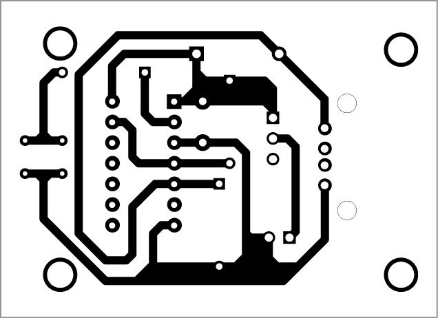
Download PCB and component layout PDFs: click here
Alternatively, you can assemble the circuit on a perfboard. If you are designing your own PCB, maintain compactness and adhere to the advice given in the piranha LED datasheet.
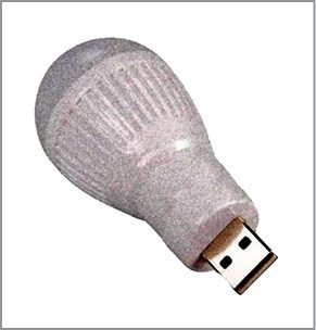
This circuit can be fitted into a bulb-shaped enclosure as shown in Fig. 7. Although a 4V, 500mAh SMF battery is used in the prototype, you can try any other low-profile 4V lead-acid battery, even a type with lesser current rating (<500mAh) would do.
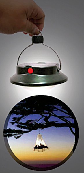
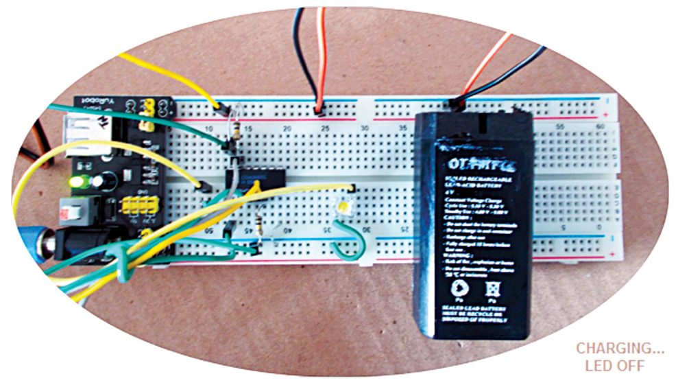
This night-lamp (Fig. 8) can be used as a portable lighting equipment (torch, headlamp, lantern or tent-light) to make your camping, fishing and other outdoor adventures simpler and more enjoyable. Author’s prototype wired on a breadboard is shown in Fig. 9.
Notes.
1. Remaining switches of IC1 (IC1C and IC1D) can be used to drive more piranha LEDs by making similar connections.
2. Maximum voltage available from the fully-charged battery is about 4.2V, and Vf of the piranha LED used is 3.2V. Based on these observations, value of the series resistor (R2) is set to 56-ohm.
T.K. Hareendran is an electronics hobbyist, freelance technical writer and circuit designer

code please????
For this project, no code is required.
Thanks a lot, Can I use this circuit with 5 “5630 SMD ” LEDs in parallel. Any change required for maximum brightness and I have 18650 lithium ion batteries can I use this with the circuit.