


 By setting up a webcam view illuminator over your laptop’s webcam your online conversations can become more enlightening. This clip-on light improves the quality of webcam photos and videos in low-light situations. The USB-operated webcam view illuminator detects low-light level automatically and switches on the power LED.
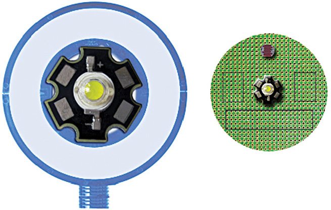
Fig. 1 shows how it can be affixed over the laptop’s webcam.
Circuit and working of Webcam View Illuminator

The circuit diagram of the webcam view illuminator is shown in Fig. 2. It is built around a USB connector, Schottky diode 1N5817(D1), comparator LM311 (IC1), 5V single changeover relay (RL1), current regulator AMC7135 (IC2), white power LED (LED1) and a few other components.

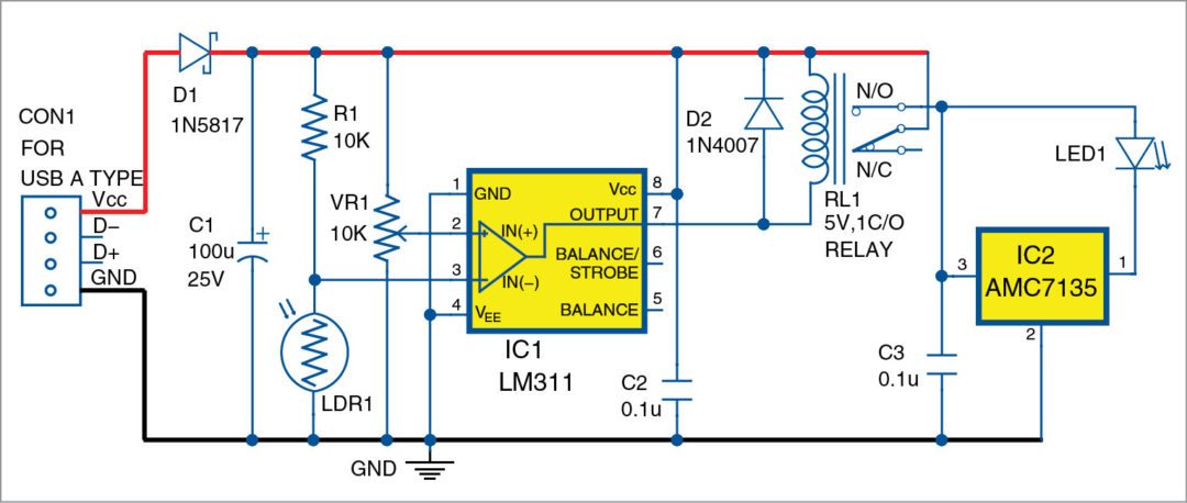
For driving LED1, the advanced current regulator AMC7135 (IC2) is used here. AMC7135, available in SOT-89 and TO-252 packages, is a low-dropout current regulator rated for 350mA constant sink current. The driver circuit takes power from the input supply and sends it to LED1. Constrained to a particular current, LED1 settles in at its forward voltage for that current and the rest of the voltage from input supply can be handled by the driver chip.
Standard photo resistor or light-dependent resistor LDR1 is connected to inverting input of IC1. It is used to detect the ambient light level. Resistance of LDR1 is low when sufficient light falls on it. So voltage at IC1’s inverting input pin 3 is low and at its output pin 7 is high. This de-energises relay RL1 connected at the output pin. This, in turn, cuts off the 5V supply to IC2 and the 1W LED1 goes to off state.
When little or no light falls on LDR1, output state of IC1 is reversed, thereby energising relay RL1. This action turns on IC2 and LED1 glows.
Since IC2 is an SMD chip, it is better to use the PCB’s copper track as its heat-sink. And, if IC2 and LED1 are placed on separate circuit boards (not recommended), value of capacitor C2 should be increased up to 1µF.
Light-sensing levels on LDR1 can be adjusted using 10-kilo-ohm potmeter (VR1). Coil of the relay must have a very low operating current (not more than a few milli-amperes).
Construction and testing of Webcam View Illuminator
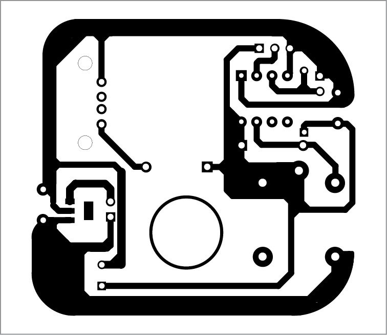
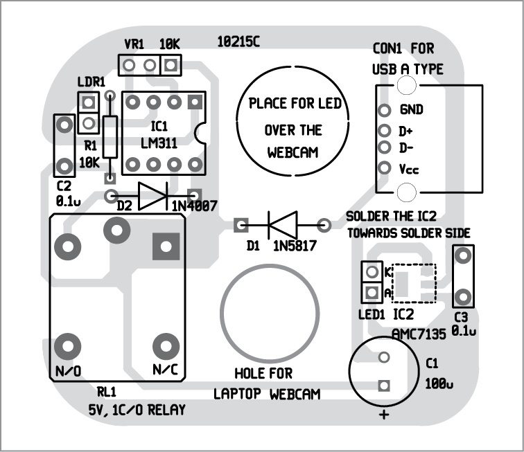
An actual-size, single-side PCB pattern for the webcam view illuminator is shown in Fig. 3 and its component layout in Fig. 4. After assembling the circuit on the PCB, enclose it in a box such that you can connect the USB port to the computer.
After construction, fix the PCB on the laptop in such a way that hole shown in the PCB does not interrupt the IR rays. LED1 is just above the hole and activates when there is insufficient light. Place the LDR1 in such a way that normal light falls on it but LED1 light does not fall on it. The front panel of the box as per author’s suggestion is shown in Fig. 5.
As the finished system is a small and easy-to-use portable LED light, it can also be used for interior and exterior applications where a standard USB port is available. For example, you can use this as a book-reading light by using a smartphone power bank/USB mobile phone charger. However, try to use a suitable light diffuser with the white power light source for effective protection of your eyes.
Download the PCB and Component Layout PDFs: CLICK HERE
T.K. Hareendran is an electronics hobbyist, freelance technical writer and circuit designer
