


 Smartphone batteries don’t last for long, and charging cables, which can break after a few months of use, can be annoying.
Wireless Chargers can be a convenient alternative – you simply set it and forget it. But how does it work, exactly?
While wireless charging may seem like a recent invention, its origins date back more than 100 years to the famous Serbian-American inventor, Nikola Tesla.

Working Principle
In the late 1800s, Nikola Tesla successfully transmitted electricity through the air. He used a process called resonant-inductive coupling, which works by creating a magnetic field between a transmitter (which sends electricity) and a receiver (which receives the electricity) to power light bulbs in his New York City laboratory.
A few years later, he patented the Tesla coil – a tower with a coil at the top that shot bolts of electricity. Tesla had much grander visions of a wireless power grid, but these dreams were never realized.
The same basic principle of inductive charging applies to smartphone wireless charging.
Bill of Material:
| COMPONENT NAME | QUANTITY | DESCRIPTION | COST IN
APPROX. |
| 0.3 – 0.4mm Enamelled Copper wire | 5 Metres | For Transmitter & Receiver Coils | 250 |
| Resistor 1K | 1 No | For current limiting | 1 |
| Transistor BC-547 | 1 No | For Switching | 10 |
| LED | 1 No | For Half Rectifier | 3 |
| USB Cable | 1 No | For Charging mobile | 50 |
| 9V battery with connector | 1 No | For Transmitter power supply | 20 |
| TOTAL IN RS | 33 |
You can use Stepdown Transformer (230/5V-1A) with DC rectifier also.
Designing Process:
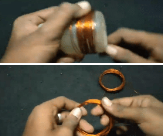
Step 1: Designing Transmitter & Receiving coil
Here, I have taken one plastic bottle (8CM dia) for making a coil. You can use PVC pipe or any other material for making coil like shapes. Wound 15Turns Enamelled copper wire over the material. After 15 Turns need to terminate and again wound 15 Turns of copper wire (like Centre Tapped Transformer).
For Receiving coil, Similarly Wound 15 Turns of enamelled copper wire and make it.
Step 2: Connections
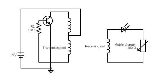
Now ready for connections, in my circuit I used BC547 NPN transistor for oscillator. You can use TTC5200 Transistor for better results.
Connect Transistor base through 1K resistor for current limitation. The center tapped coil is connected to Positive terminal of battery and Negative terminal connected to Transistor Emitter terminal. The other two end of transmitter coil are connected to Transistor collector terminal and base terminal through current limiting resistor.
Receiving coil ends are connected to USB cable through LED (Here LED is used for indication and half wave rectifier purpose).

Circuit Diagram:
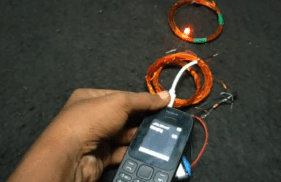
Step 3: Principle of Working
The Transmitter coil is connected to battery through Transistor an DC current is converted into frequency (Oscillating circuit). The oscillating current inside the transmitting coil causes the coil to emit 1Mhz magnetic field. This oscillating magnetic field induces an electrical current in the receiving coil. The induced
current is alternating current so it need convert into DC for mobile charging applications so I used LED for indication and rectification purpose.
Nice