


 A smartwatch monitors and tracks the wearer’s location and health data besides showing time and date. But it usually costs ₹5,000 to 50,000 and is not programable. The smartwatch suggested here can be made for less than ₹2,000 and will perform all the basic smartwatch functions. It can even be programmed for additional functions and customized according to your need to track, for instance, your blood oxygen percentage.
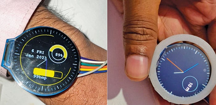
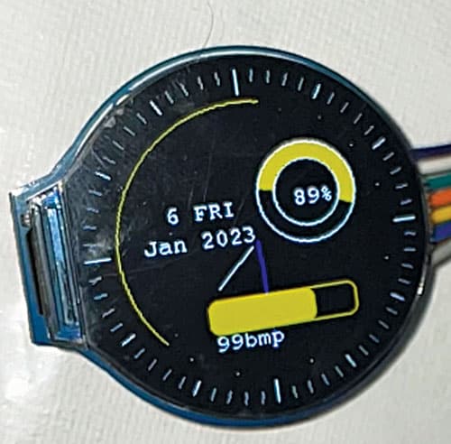
This smartwatch is based on a Wi-Fi chip that helps to customize it as part of a mesh network. It can thus track a large number of people’s health data connected to the mesh network. There are many more functions and possibilities that can be implemented on it by programming it accordingly. The author’s prototype of the smartwatch is shown in Fig. 1.

Bill of Material
See the Bill of Material table for the complete list of components.
| Bill of Material | ||
| Components | Quantity | Description |
| ESP12F (MOD3) | 1 | SMD Wi-Fi SoC chip |
| MCP73812T (MOD4) | 1 | Battery charging IC |
| Round LCD (MOD1) | 1 | GC9A01 round LCD display |
| MAX 30100 (MOD2) | 1 | SpO2 and heart sensor |
| LED | 1 | SMD LED |
| Resistors: 470Ω (R2), 2kΩ (R3), 100Ω (R1) | 1 | SMD |
| Capacitor 4.7µF (C1, C2) | 2 | SMD ceramic |
| 2-pin jumper (JP1) | 1 | Jumper pin |
| Micro USB | 1 | SMD micro USB female |
| Switch (S1) | 1 | SMD slide switch |
| 3.3V battery | 1 | Microsize for watch |
| 3D printed case | 1 | Body for watch |
Circuit Diagram
The circuit diagram of the programmable smartwatch is shown in Fig. 2. The watch is built around a round-shaped LCD (MOD1), MAX30100 (MOD2), ESP12F (MOD3), MCP73812T (MOD), and a few other components.
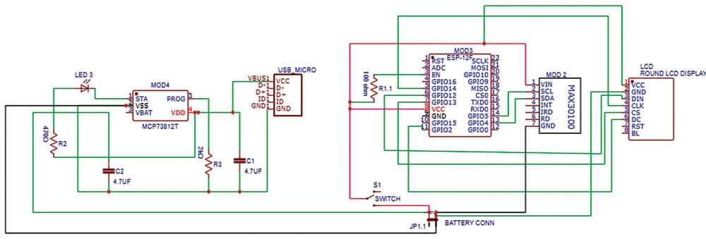
Connect the components as per the circuit diagram with the battery +ve and -ve terminals connected to jumper JP1. The left side of the circuit in Fig. 2 is for battery charging. To charge the battery, move slide switch S1 connected to the JP1 pin to its offside and charge the battery using a micro USB charger. After charging, move the switch back to its on position.
Programming Smartwatch
Prepare code for the smartwatch so that it can accept the data and show it the way you want. To use Arduino for coding, download the latest Arduino IDE. Since the IDE requires an ESP board to program, go to the ESP website and follow the instructions to install the ESP board on Arduino IDE.
We need various libraries to interface with the LCD and for getting time from the network.
So, open Library Manager and install NTP client, MAX30100, and Arduino GFX libraries.
After installing libraries, interface the round LCD display using the Arduino GFX library and include that in the code. We need the NTP client to get time from the Wi-Fi network, so include that as well in the code.
As we need to interface the MAX30100 heart sensor, so include that library as well.
After including all the libraries, set up the code for the hardware SPI bus pins and board type. Here we are using the ESP826612F chip, so set the board as ESP8266 and then set the DC and CS pins of the LCD display.
You can use any free pin on ESP CHI. (We used pins 2 and 13.)
Next, set the display of the display driver GC9A01 in the code. Setting the board and pins for the display is shown in Fig. 3.

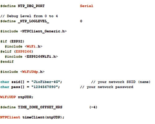
Now we need to set the Wi-Fi SSID and password for the NTP server so that the watch can connect to the Wi-Fi of our phone or the home Wi-Fi to fetch the time from NTP client-server.
So, we create the setup function where we initialize the I2C communication with the MAX30100 sensor, the SPI communication with the LCD display, and the NTP server for the clock. Wi-Fi setting for the NTP server is shown in Fig. 4.
Creating GUI for Watch
Create a loop function where the sensors and time data can be updated in real-time. Then create an interface and look for the smartwatch to display the health data, date, and time data in real-time.
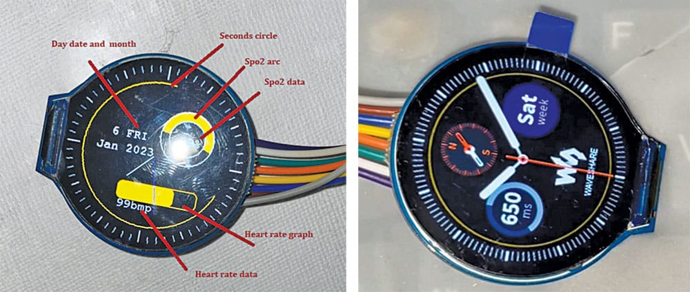
You can code and make any style of GUI of your choice for the watch. The author used the circular mark with hands for minutes and hours with a circular arc that decreases with every second to show the time in seconds. We used an arc and circle with text to display the SpO2 value and a round rectangle for displaying the heartbeat data. He used text to display the current day, month, and other time-related data.
After preparing the code, upload the code to the ESP12F chip by selecting the right board and port number. The chip needs to be set to boot mode and connected to the FTDI programmer for that. (To know how to upload code to the ESP12F chip, refer programming part of an article on IoT health stickers published in the December issue.)
Construction and Testing
Before assembly, refer to Fig. 5 through Fig. 8. Place ESP12F behind the display and MAX3011 sensor carefully such that their terminals and connection points do not touch and are short. Get the watch’s circular case and fit the components inside it. If you wish, you can design your own watch case and 3D print it. You can download the Gerber file and PCB design to get the watch ready.
Create an interface for the smartwatch to display health data, date, and time data in real-time. You can code and make any style of GUI of your choice.
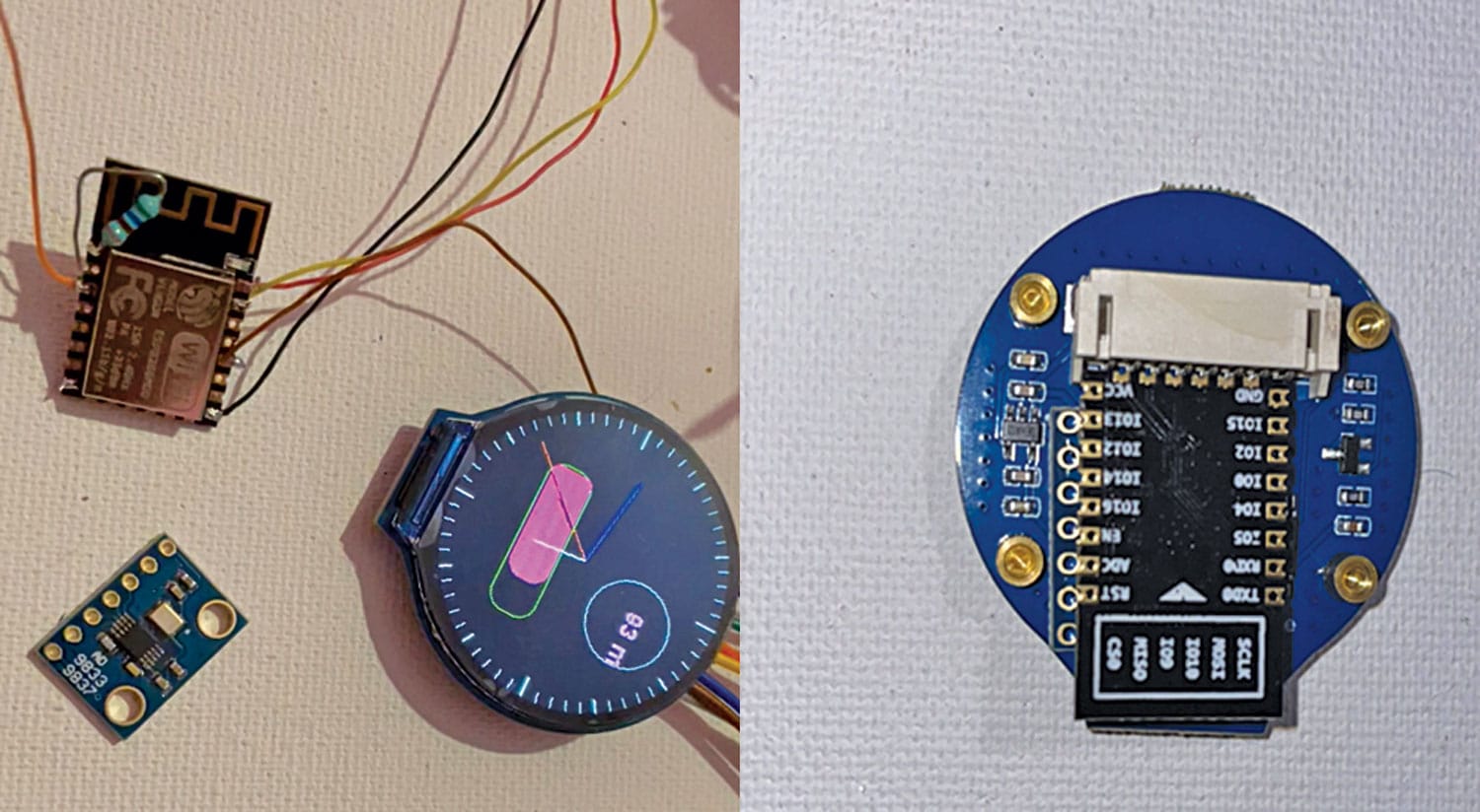
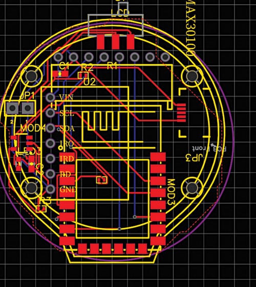
Fig. 5 shows the PCB design for the watch. Soldering of the ESP12F chip with display and placing the ESP chip behind the watch is shown in Fig. 6. Smart watch 3D case design is shown in Fig. 7.
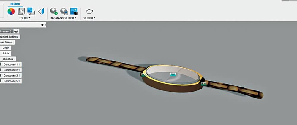
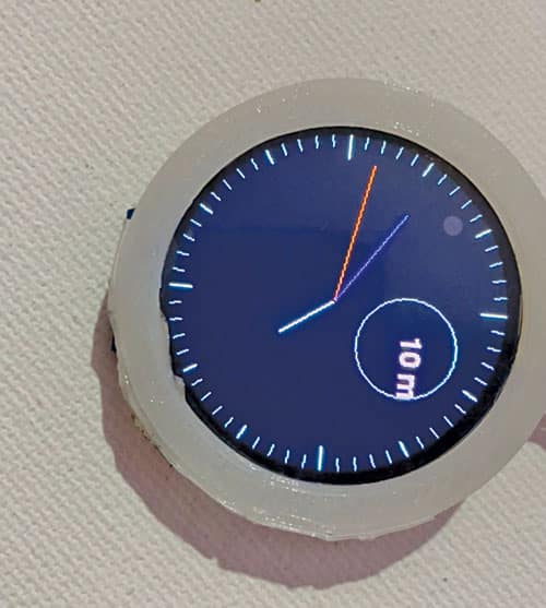
Fig. 8 shows the smartwatch inside a 3D printed case.
After preparing the code, upload the code to the ESP12F chip by selecting the right board and port number. The chip must be set to boot mode and connected to the FTDI programmer. The GUI of the watch designed by the author is shown in Fig. 9.
To test, power the watch with a 3V battery and wait till it connects to Wi-Fi and fetches the current day, date, and time from the NTP server. It is now ready to start showing the health data beside time. The final look of the programmable smartwatch with fitness tracking is shown in Fig. 10.
Note. This is the first version of the smartwatch design. An advanced design with additional functions like a real-time Wi-Fi analyzer, web health GUI, and many more are getting ready for publication in the upcoming issue.
Till then check out more such interesting DIY electronics projects.
Download source code
Ashwini Kumar Sinha is an IoT and AI enthusiast tech journalist at EFY

Super project
your name on @EasyEDA. also is pcb design made public ?
Kindly elaborate your query.
What is the type and capacity of the battery used? Bill of materials 3.3V battery 1 Microsize for watch. In the description it is mentioned 3V. How much time can I operate with the mentioned battery?