


Optical fiber links are the backbone of all telecommunication companies to carry their traffic. The three most important necessities for the people in this modern world are internet, telephone and television. The usage of internet is increasing day by day and every person in this world wants to communicate any information without any delay. So, all the telecommunication companies increased their transmission capacities with the help of optical fiber technology. Presently, optical fibers are used for carrying the internet, telephone and television signal. Multiplexing is one of the powerful techniques in optical fiber communication, it is multiplexing the multiple information from different source and transmit it over a single optical fiber. PDH (plesiochronous digital hierarchy), SONET (Synchronous optical networking), SDH (Synchronous Digital Hierarchy), DWDM Dense Wavelength Division Multiplexing and OTH ( optical transport hierarchy )are the digital transmission technology, using optical fiber as a medium for the communication. DWDM and OTH are the very advanced and high capacity digital transmission technologies, using different multiplexing techniques to carry their information. The real block of present optical fiber communication network is shown in figure 1.
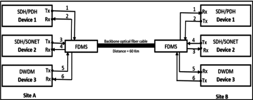
By referring the figure 1, three technology devices (SDH/PDH, SDH/SONET and DWDM) from site A are communicating with the same devices at site B. The medium used for this communication is optical fibers. The basic block elements in site A and site B are digital transmission devices (PDH/SDH/SONET/DWDM), optical modules, patch cables, FDMS and optical fiber cable. Each technology device contains service cards, line cards, power interface unit and fan unit. The detailed description of each important block is explained in a following section.

Fiber Optic Module
SFP (Small Form Factor Pluggable) stands for small form factor pluggable, it is an optical transceiver module used in optical fiber communication, to convert optical signal to electrical and vice versa. Each optical module operates on different wavelength and different power levels. The popular wavelengths used for long distance communication are 1310nm and 1550nm. The attenuation level (water peak) for 1310nm and 1550nm are very less as compared with the other wavelengths, especially in the long-distance communication. Each unidirectional SFPs contains separate transmit and receive ports and it requires separate fibers to connect the transmit and receive port. Bi-directional SFP is differ from unidirectional SFP, only one port dedicated for both the transmission and reception. By referring the figure 1, device 1 at site A (Fiber 1-Tx and Fiber 2-Rx) communicating with device 1 at site B (Fiber 1-Rx and Fiber 2-Tx). Similarly, device 2 and device 3 at site A communicating with the device 2 and device 3 at site B.
Patch Cable
Patch cable or cord is the optical patch cable used to connect the end to end optical devices. By referring figure 1, patch cables are connected between devices (device 1, 2 & 3) and FDMS (Fiber Distribution and Management System). There are number of connectors used for patch cable, some of the popular connectors are LC, SC, FC and Euro. In this work, LC to SC connectors were used to connect between technology devices and FDMS block.
FDMS (Fiber Distribution and Management System)
FDMS stands for fiber distribution and management system. It is a passive device, used in optical network to interconnect the fiber from technology devices to the backbone optical fiber cable. The outdoor fibers and indoor fibers are interconnected in FDMS device by using splicing technology. Some of the popular FDMS types presently used in telecom are round connector, square connector and euro connector. In this work, only square type FDMS used at both sites A and B.
Optical Fiber
By referring figure 1, site A is transmitting information to site B in the form light pulses through a fiber cable and vice versa. Fibers are made up of glasses and plastics, and it is very thin in size. The advantages of using optical fiber are high capacity, immune to interferences and long-distance communication. Single mode and Multimode are the two types of optical fiber. All the dark fibers working on single mode and the size of the core is 9µm in thickness. The losses per km in optical fiber depends on the wavelength used and the standard of the fiber. G.652.C &D is the single mode standard and there will be no water peak in this standard. The standard loss/km for 1310nm is 0.4dB and standard loss/km for 1550nm is 0.25dB. The possibilities of communication fail between any two nodes or sites depending on many factors. Some of the basic and important factors are discussed in a following section.
Reason for communication Fail:
1. The fiber break occurs between site A and site B.
2. More attenuation during the transmission
3. Fiber patch cables are not connected at the SFP ports
4. Laser shutdown at site A or site B.
5. Board/Card faulty.
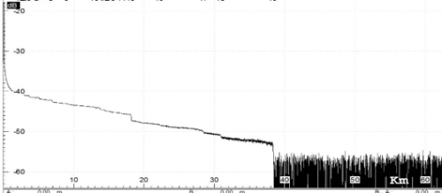
The fiber breaks can be easily identified with the help of OTDR (Optical Time Domain Reflectometer) device. The OTDR is an electronic device used to find a fiber span. All the telecom companies using this device, to spot the exact location of fiber break, heavy losses and attenuation per kilometer. The optical pulse signal sends into the fiber scattered back towards the OTDR device because of the disruptions such as fiber break, bends, splices and connectors. Then the back scattered light will be processed and analyzed, results will be displayed on the OTDR screen. The OTDR can calculate the total length of the fiber by using a simple formula,
Total length of the fiber=ct/2n
Where c = Speed of light.
t = Time difference between pulse sent and pulse received.
n = Index of refraction.
So, the health of the optical fiber link can be monitored with the help of an OTDR.
Results
In this work, the two-real backbone optical fibers are tested and analyzed with the help of OTDR device. The fibers considered for testing are fiber 5 and fiber 6 (device 3). The actual length of the fibers between the site A and site B is 60Km. Any breaks between the sites can be identified with the help of an OTDR. Wavelengths considered in this testing are 1310nm and 1550nm. The trace results of fiber 5 and fiber 6 are shown in figure 2 (2a, 2b) and figure 3 (3a, 3b) respectively.
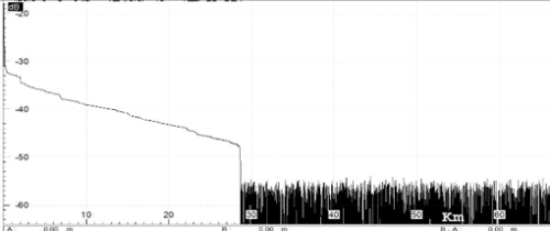
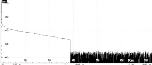
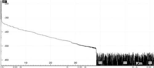
The total loss, actual length, OTDR length and wavelength used are shown in Table 1.
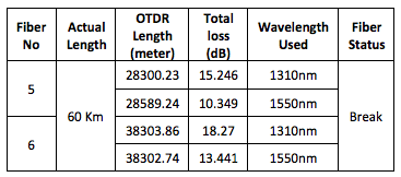
By referring the figure 2 and figure 3, the losses of the fiber increasing with the increase of kilometers. Comparatively, the losses in 1550nm are less than the 1310nm (refer the table 1). The standard loss of the fiber at 1550nm is 0.25dB/Km and fiber at 1310nm is 0.4dB/Km. By referring Table 1, the actual length of the fiber 5 and fiber 6 differs from the OTDR length, meaning that there is a fiber break and communication not possible between the sites (device 3/ DWDM). In this work, the real backbone optical fiber communication is discussed and it yields a new understanding about the fibers, wavelengths and OTDR device.

wow just want to say very nice blog. Very helpful to me. Thank you for your wonderful blog. Now i am surely known that is was not know previously.
Hi Ranbir,
Thank you for your comment. You can ask if you have any queries in this article.