In India, electrical distribution infrastructure is not well extended in rural areas. However, with advanced development in power electronics switching and control devices, it is now possible to replace an existing AC power distribution network with a DC power supply for better energy efficiency. For this, a case study of actual load data has been done at academic buildings of Matoshri College of Engineering, Nashik. Energy-efficiency analysis on different loads has shown that, if an existing AC power distribution network is replaced by a DC distribution network, considerable amount of energy can be saved.
Current scenario
The electrical power distribution system at the end of 19th century was based on DC technology. This Edison DC distribution system had the disadvantage that power generating plants feeding heavy distribution conductors and consumer loads tapped of these. This system operated at the same voltage level throughout.
But to have a better option, a three-wire system was also used to save the cost of the copper conductor. The three wires were at 110, zero and -110 volts relative potential. 100-volt lamps could be operated between either +100 or -100-volt legs of the system and zero-volt neutral conductor that carried only unbalanced current between the positive and negative sources.
For fast growing power electronics development, it is possible to completely replace the existing AC distribution network with DC distribution network, from the point of view of today’s power system scenario at distribution side. Most of the loads on distribution side are of DC type and, unfortunately, these all are fed by an AC-type supply distribution system involving a number of energy-conversion stages.
In case of AC type there should be source synchronization, which is not required in case of DC. DC can be drawn directly from solar, wind and the grid by the loads, depending on which source is available. Harmonic issues and phase-balancing problems are not present in a DC system. It offers a lower cost of ownership in building wiring, copper and connectors along with an increase in efficiency of eight to ten per cent, which is truly significant.
A proper distribution system offers higher efficiency and the potential to extract power from multiple available sources. Then there are benefits that are not as immediately apparent. Most back-up energy sources such as batteries and flywheels are inherently DC.
Further, telecom and server loads run on DC, so there are fewer intermediate efficiency-robbing stages, along with greater reliability due to fewer potential points of failure with the DC approach. According to Central Electricity Authority (CEA), India has a shortage of around 11 per cent peak demand and more than 24 per cent T&D losses. In most rural areas, electricity is not available for more than eight hours a day, so it is necessary to move towards energy-efficient techniques with renewable energy support.
Low-voltage DC power distribution system topologies
A low-voltage DC (LVDC) system is of two types, accordingly to conductor polarities:
Unipolar LVDC system.
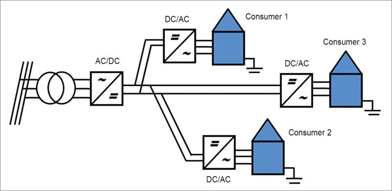
In this type of distribution system, voltage level throughout the system is the same. The two-conductor system has one conductor at positive polarity and another at zero or neutral polarity. Entire load on the distribution system is connected at this voltage level, as shown in Fig. 1.
Bipolar LVDC system.
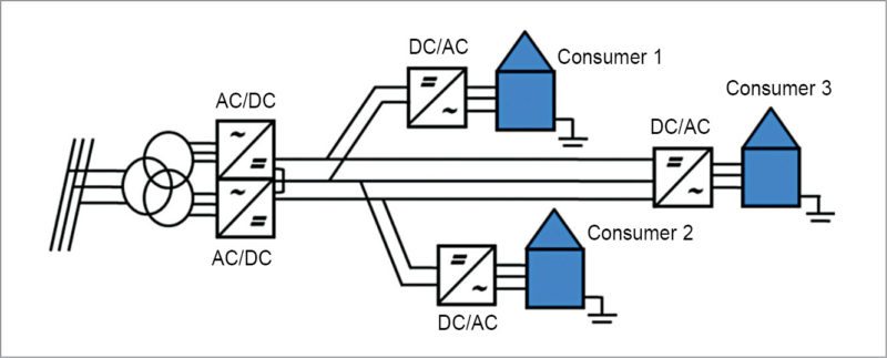
A bipolar LVDC system is a combination of two series-connected unipolar systems. In this system, it is the choice of the customer to connect to the appropriate voltage level. The choices are:
1. Positive to neutral polarity
2. Negative to neutral polarity
3. Positive to negative polarity
4. Positive to negative polarity with neutral connection
Fig. 2 shows the possible alternatives for a consumer connection. Customer connections 1 and 2 can lead to an unsymmetrical loading situation between DC poles in the system. Possible over-voltage can be restricted with a cable cross-section selection. Connections 1 and 2 are used in studied ±750V DC bipolar system. Main lines of the system contain all three conductors but customer connections have two-wire cables connected between positive or negative poles. Therefore customer supply voltage is either +750V DC or -750V DC.
Energy efficiency analysis of AC/DC, DC/DC and DC/AC conversions
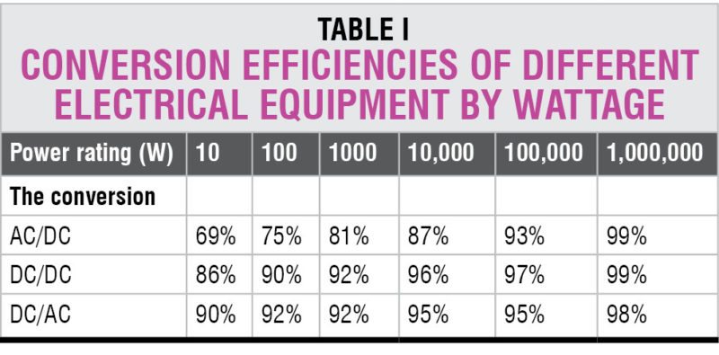
According to the survey of different products in the market, some conversion efficiencies for different wattage ratings are given in Table I, which can be further used for calculations.
Losses calculation
Loads in the building.
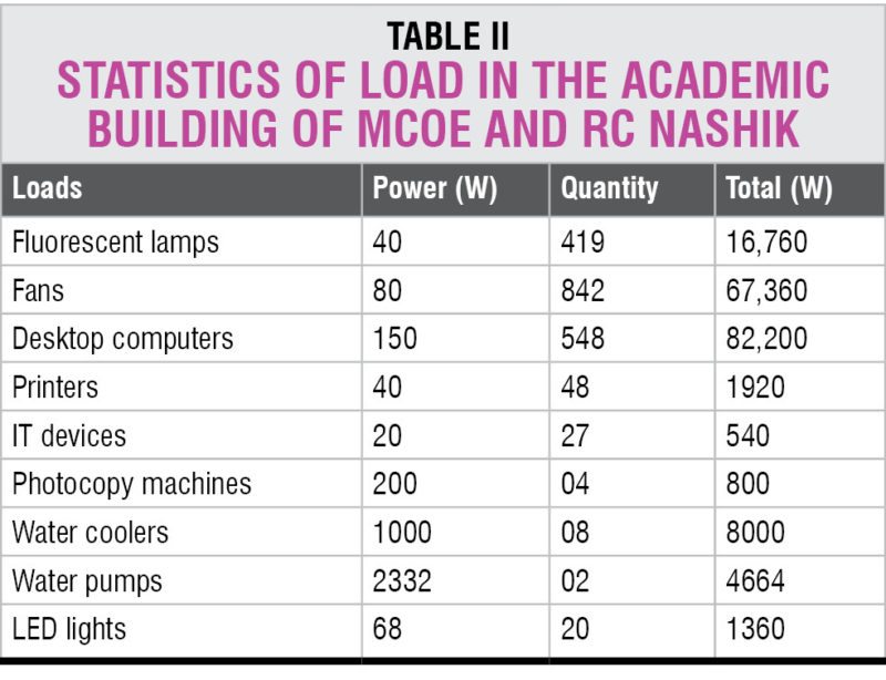
Academic buildings consist of different connected loads, broadly mentioned in Table II with their wattage ratings. From Table I it is clear that, according to the wattage rating, conversion efficiency of every electrical equipment is different. Now, to calculate the total energy consumed by each equipment, a site survey was done. According to the site survey, total electricity consumed by a particular load is given in Table II.
<1–nextpage–>
Power supplies of loads in the building.
From the above-mentioned data of connected loads for the buildings, conversion efficiency formulae for different loads are given as follows:
Desktop computers.
Efficiency for desktop computers on existing AC supply is given by:
ηAC= ηUPS×ηT×ηAC/DC×ηDC/DC×ηFeeder …….. (1)
If the same is used to supply from DC power system, power efficiency is:
ηDC= ηUPS×ηDC/DC×ηFeeder …….. (2)
where ηUPS is the power efficiency of UPS (75 per cent taken here by measurement), ηT is the power efficiency of transformer, ηAC/DC is the power efficiency of AC/DC, ηDC/DC is the power efficiency of DC/DC and ηFeeder is the power efficiency of feeder, which is 100 per cent.
Other loads.
Like desktop computers, it is possible to calculate the power conversion efficiency for AC and DC supply for all other loads.
For fluorescent lamps:
ηAC= ηFeeder …….. (3)
ηDC= ηDC/DC×ηFeeder …….. (4)
For printers and IT devices, these efficiencies are calculated using equations (1) and (2).
For LED lights and photocopy machines:
ηAC= ηAC/DC×ηDC/DC×ηFeeder …….. (5)
ηDC= ηDC/DC×ηFeeder …….. (6)
Similarly, power efficiencies can be calculated for all the loads, and their calculated values are summarised in Table III.
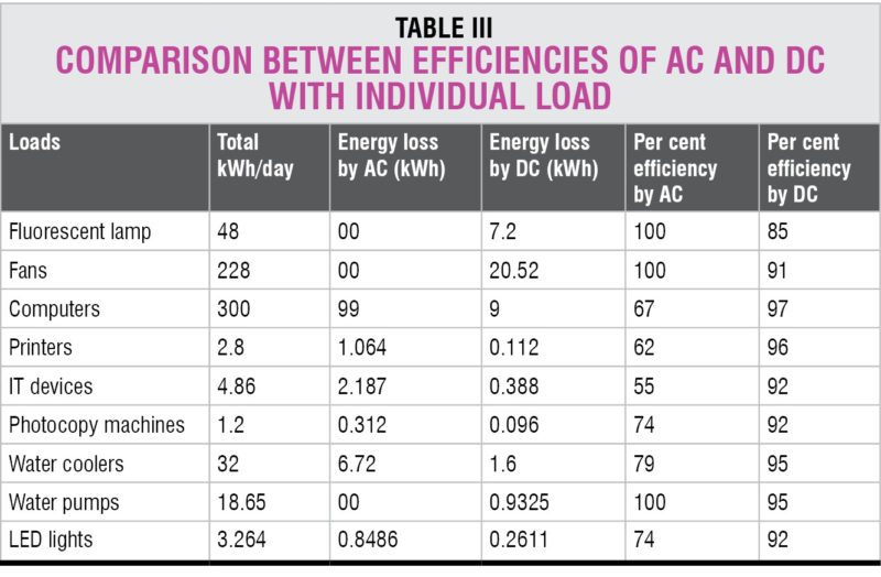
It is clear from the above analysis that in a distribution system, where most loads are of DC type, a DC distribution system works quite efficiently. Also, effective energy saving of 18 per cent is possible.
Calculations for energy-conversion efficiency of a building have been established for various loads. During the conversion from AC/DC, DC/AC and DC/DC, power losses are calculated with efficiency for AC and DC supply with proper comparison.
Compared to an AC distribution system, a DC distribution system has 18 per cent more efficiency. Thus, a DC distribution system with bipolar DC feeder has a great future in India to achieve Late Dr A.P.J. Abdul Kalam’s Vision of 2020.


