


We take our batteries for granted and often misuse them, unknowingly. But there is much that goes behind designing a battery and, especially, its management system, without which it can run amuck. Read on to find out how the battery management systems are designed
To a user a battery looks like a black-box, which magically produces electrical energy. And it looks like no active control is required for the battery to perform well. The truth, however, is that most batteries require some kind of electrical control to keep them from going bad and have a long working life. For some battery chemistries this control may be intermittent and simple, while for others it could be continuous and essential.

An intelligent system that takes care of the batteries is called battery management system (BMS). Here we shall discuss some essential parts of a BMS that apply to most types of batteries, and specifically to lithium-ion (Li-ion) based batteries.
A BMS manages the circulation of electrical energy to and from the battery and the distribution of this energy across its constituent cells. It tries to manage the charging and discharging of the battery to achieve some health goals for the battery. The most basic goals for a BMS are:
- Always monitor the health of the battery
- Control its charging and discharging to maximise battery health and performance
- Protect the battery by maintaining its cells’ voltage within the specifications
- Report the battery’s health status to the user
The BMS is a complete system and, like any other embedded system, it has following important parts:
- Supervisory control element (microcontroller and/or application specific integrated circuit)
- Sensors for voltage, current, temperature, and vibration
- Controlled switches (MOSFET/IGBT/relays/contactors)
- Indicators (optional)
- Communication peripherals, either as part of the MCU or a separate IC
Let us first understand the various aspects that need to be controlled/monitored, so that we can later on assign each of these jobs to specific entities of our hypothetical BMS. Before we start, remind yourself of the adage, Design is all about choices and trade-offs!
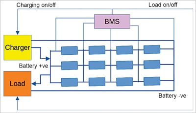
A typical connection diagram of a 4S3P battery type is shown with its BMS in Fig. 1. Please notice the following important things here:
- The BMS is an integral part of the battery. Unprotected Li-ion batteries are unsafe and unusable
- The BMS is connected to each cell pack (cells in parallel) in series
- The BMS controls the charging and discharging of the battery pack
- As the number of series string cell packs increases, so does the BMS complexity
Monitoring health of the battery
Battery health has multiple parameters, the most essential of which are its terminal voltage, charge capacity, and cell temperature. So, monitoring battery health involves monitoring these parameters continuously.
Voltage monitoring
A battery, as the name suggests, comprises individual electrochemical cells that are connected in series or parallel. So, each cell voltage should also be monitored. Let us understand what the cell voltage represents.
The specific energy (or energy density or energy per unit volume) of a particular cell chemistry is unique to its molecular composition. This specific energy directly affects the terminal voltage of a cell. Thus, higher the terminal voltage of a particular chemistry, higher is its specific energy.
To sustain the reversible nature of the cells’ electrochemical properties, it is necessary that the energy content in the cell should not fall below a certain level or rise above a certain level. In simpler words, to keep the cells healthy, and in turn the battery healthy, it is essential to keep the cells’ terminal voltage within a given voltage envelope.
This safe voltage envelope (SVE) is different for every chemistry. For example, the lead-acid chemistry has an open circuit voltage (OCV) of approximately 2.1V and an SVE of 1.8V to 2.35V. The lithium-iron-phosphate (LiFePO4) cell has an OCV of approximately 3.2V and an SVE of 2.5V to 3.65V.

Since each cell of a battery is made individually, and because it is impossible to make completely identical cells in a batch or across batches, nominal cell voltage of each cell may be different inside the battery. Thus, if a battery has 100 cells, would the designer have to monitor voltage for all the cells? Just ponder over it. We shall try to answer this while looking at energy redistribution strategies later in this article.
Charge capacity monitoring
The charge capacity of the cell is of primary importance when cell health is considered. The interesting part of the charge capacity is that for most chemistries it is reflected in some part as the terminal voltage of the cell.
In case of Li-ion cells, the change in terminal voltage with respect to its charge capacity is quite flat. This means that the terminal voltage does not change much with reduction in charge capacity. Thus, the depth of discharge (DoD) levels or the state of charge (SoC) levels cannot be faithfully calculated all along their charge/discharge curve based solely on the terminal voltage.
If we consider the discharge curve of a Li-ion cell, major changes in the OCV of the cell occur only at the extreme ends, and all through the curve the OCV almost stays flat with change in the DoD. This is in stark difference from lead-acid cells, where the OCV changes quite a bit with increasing DoD.
This unique nature of the Li-ion cells means that a BMS must use an advanced approach to ascertain the running DoD levels. The typical BMS achieves this by using multiple techniques, such as the use of high granularity analogue front-end and using Coulomb Counting to track the charging and discharging levels and rates. Some advanced BMSes may also employ a square wave load at a frequency of 1Hz to 1kHz, to get an idea of the internal resistance of the battery and thereby infer its state of charge.
Cell temperature monitoring
Another parameter to monitor is the cell temperature. Cell temperature affects the electrochemical reactions and intercalation processes in the cell. An excessively high cell temperature can result in gasification in lead-acid cells and can result in a thermal runaway failure in Li-ion cell chemistries. An excessively low temperature can permanently damage a Li-ion cell.
This means that a BMS should monitor cell temperature all the time. But doing this for each individual cell would be quite sub-optimal for the overall battery design. This is where the BMS designer must take a call on placement of temperature sensors. It must be assumed by the designer here that cell temperature (either internal or ambient) will affect adjoining cells as well, and so overall temperature of the battery can be estimated by using only a few temperature sensors.
Ideally, once the battery is fabricated, a temperature distribution analysis must be carried out while the battery goes through at least a single charge and discharge cycle. Such an analysis will show the hot spots of the battery and would help the BMS installer to decide on points of installation of the temperature sensors.
Simpler BMSes either provide a single temperature sensor for the entire battery or do not provide any. A good and responsible BMS should have at least 4-5 temperature sensors. Typically, the temperature sensors used for BMSes are resistive temperature devices and sometimes thermo-couple modules. Advanced BMSes may also provide ways to control the battery temperature by either using forced air/liquid cooling or heating up the battery using Peltier elements.
Controlling charging and discharging
Charging and discharging a battery of cells is the primary process that the battery goes through. Controlling the process of charging and discharging ensures that the battery remains healthy for the longest time possible. However, this kind of control is mostly an on-off type control.
Discharging depends mostly on the load connected to the battery and the BMS has no control over the load, and so it controls the discharge rate by limiting the discharge current. Similarly, the BMS also does not have any control on the charger capacity, and it only controls the charging rate by limiting the charging current. The BMS almost stays transparent to charge movement until the charge or discharge current reaches the specified maximum value, at which point it kicks-in and disconnects or reconnects the load or source from the battery.
It is interesting to note that the maximum charging and discharging rates of a battery depend directly on its capacity. This capacity is typically expressed in the unit of ampere-hour (AH), which is mostly a glorified unit of charge (remember, Q=I×T). Different batteries having the same nominal OCV can differ from each other based on their capacities. For example, a standard 12V battery is available in various capacities, such as 7AH, 35AH, 50AH, 80AH, 100AH, and so on. Battery cell capacities are typically specified in mAH, which is milli-ampere-hour.
Since the current capacity of the above batteries is different, this means the BMS used for each one of them must also be different. The BMS designer, therefore, must specify a current capacity against which the BMS will work. BMSes are always specified in terms of the typical voltage and maximum current that they can handle.
The BMS voltage is usually specified in terms of the series connection of the constituent cells. For example, a 3S Li-ion BMS means that it expects to be connected to a battery having 3 Li-ion cells connected in series. This means that when choosing a BMS for battery, the user must look at both the battery capacity and the application requirement, and choose a BMS such that:
Battery Current Capacity≥BMS Current Specification≥Application Current Requirements.
Some BMSes allow a single connection point for charging and discharging. This is the simplest design, while some others allow different points for charging and discharging connections. The logic behind a single connection is typically lower price. However, with only one connection point, the battery can only be connected to either the load or the charger.
With two connection points, the BMS allows connecting the battery to the charger and to the load at the same time. This is the most common scenario in our day-to-day use. But the mobile phone BMS allows use of the battery to power the mobile phone while also being charged via its USB device port.
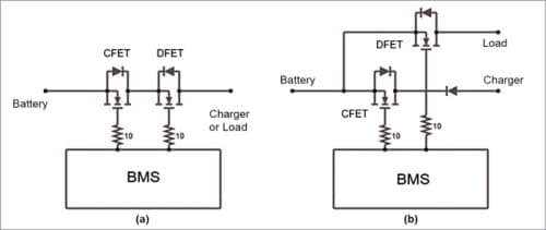
The BMS also needs to use different cut-off switches for the charge and discharge current paths of the battery. This is because the charging path is from the charger to the battery, while the discharging path is from the battery to the load, and a BMS typically uses a MOSFET (or other static switches) for connecting and disconnecting the battery from the external world.
These devices are unidirectional, so two different FETs have to be used. In this case, they are connected back-to-back and use each other’s body diode to complete the charge and discharge paths. While this allows independent control of the charging and discharging current limit, the BMS still needs to provide different connection points, in case the battery has to be connected to the load and the charger simultaneously. If there is a single connection point, either of the current limits can lead to the port being disconnected, stalling the other process as well.
Even though we can provide two connection points, the battery itself can function only in one mode at a time, either charging or discharging. Let us understand this in some more detail. The typical voltage condition of a battery system would be such that:
Charging Voltage>Battery Voltage>Application Requirement
This must hold at all times, so that the battery can accept charge from the charger and also provide charge to the application. So, if the charger is connected, while the battery is still supplying to the load, it is obvious that only a part of the charge goes to the battery, while the rest is used by the application. Thus, in this case, the battery is not in a discharging mode.
It may also happen that, if a heavily discharged battery is connected in the above arrangement, all the charge is first absorbed by the battery. Here the application suffers until such time that the battery voltage rises to a certain level and the charging supply has excess charge available to power the application. Users must have seen this happening when their mobile phones reach very low levels, and a charger is connected. For some time, until the charging indicator shows a small percentages of battery capacity (typically 2% or more), the mobile phone does not switch on completely.
When the charging voltage is removed, and the load is still connected, the battery enters the discharge mode. So, even though technically the battery may allow both charging and discharging path to be connected, the net battery current at any point can only be either positive (charging) or negative (discharging), but not both.
As mentioned earlier, the BMS also controls the charging and discharging process by ascertaining the running charge capacity of the battery by using a simple technique called coulomb counting. Coulomb counting, at its simplest, is the count of the amount of charge that is present in the battery and is a way to track the state of charge of a battery.
Mathematically, coulomb counting refers to the integral of the current over time. In discrete terms, coulomb counting is a Sigma function, that is:
∑(current_in_amps×hours_in_operation)
The BMS keeps a running record of the current levels over a given time period, and thereby tries to estimate the relative charge capacity of the battery. The important word to note here is ‘relative,’ because coulomb counting gives an account of the change in the charge capacity of the battery. Therefore, unless the BMS is calibrated at either ends of the charge/discharge curve, it is not possible for the BMS to estimate the actual state of charge or depth of discharge of the battery.
Barring a few important limitations, coulomb counting can be an effective technique to track the SoC of the battery. The limitations are: (a) the leakage current or self-discharge of the battery, which will not be registered by the BMS, and (b) the offsets in current measurements.
As already mentioned, BMSes solve these issues by using high granularity analogue front-ends and calibrating themselves at the end and start of the charge and discharge curve. Using a BMS of the same current capacity as the battery also helps in this process of tracking the SoC. Thus, at low charge capacities, the BMS can initiate a battery disconnect, even though the discharge current is less than the discharge current limit.
To know the charge and discharge current separately, the BMS may use a single current-sense element or two different current-sense elements, and this is left to the BMS designer. The BMS designer must make a trade-off here between cost and convenience of measurement. The BMS is said to be operating in the charge controller mode in this case.
Maintaining cell voltage
A battery is typically made from series/parallel combination of cells. Parallel connected cells form a local closed circuit and stay at the same voltage. Any difference in their voltage gets distributed based on the Ohms Law. However, series connected cells are not intrinsically in a closed circuit, and hence they can assume different maximum and minimum voltages. This means that a BMS needs to look at individual series cells (or packs of parallel cells) and ensure that the cells stay within their specified voltage range.
But why will cells move to different voltage levels? Here comes the law of probability of microscopic differences between cells, which compound to make one cell weak and another cell strong. A weak cell is one that gains voltage faster than others and loses voltage faster than others. Fig. 4 shows a condition where individual cell differences combine to create widely differing voltages on individual cells, whilst the overall battery voltage remains the same.
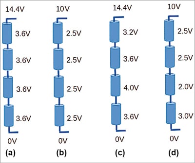
Fig. 4 shows various possibilities of charge distribution within a 12V LiFePO4 battery pack. As shown in Fig. 4(c), a weak cell (C-3) causes the battery pack to reach full charged voltage before all the cells have reached their full voltage. This causes the problem that C-3 goes out of safe voltage envelope and some other cell is left uncharged to its full voltage. Since the battery pack has reached its full voltage, the BMS would have to open its charging FET and stop any charging current.
On the extreme end, at the time of full discharge, as shown in Fig. 4(d), the weak cell (C-3) discharges much faster than other cells, because of which the overall battery voltage reaches its discharge limit before the last cell (C-4) can be discharged fully. This means the battery has spare capacity that cannot be used any more.
In practice, Fig. 4(a) and Fig. 4(b) represent cases which cannot be achieved without active intervention from a BMS, while Fig. 4(c) and Fig. 4(d) represent cases that are almost always found in battery packs.
So, the BMS tries to either expend excess energy from weak cells or redistribute energy within the battery pack to avoid cells going out of their specifications. This process of correcting the distribution of energy is quite literally called balancing. Balancing the cells by expending excess energy is best done either during or just after the charging process, so that cells being expended are also replenished and, if required, the flow of current continues, and thus it is called top-balancing.
Redistribution of energy can be done while charging or while discharging, or while the battery is not being used for any load. So, redistribution allows either top-balancing or bottom-balancing operations. Balancing by expending excess energy is carried out by connecting the weak cells across a burden resistance, which converts the excess energy into heat. The rate of balancing is limited by the resistance value. This is also called passive balancing, because only a connection to the burden resistance is required for top-balancing to happen.
Generally, since the BMS does not know which cells could be the weak ones in practice, they are designed to provide a burden resistance across each cell in the series connection. The value of the burden resistance is chosen such that balancing happens within the shortest time possible while keeping the resistance temperature within safe limits.
Redistribution of energy is much more complex because, to redistribute energy some form of energy storage device is required, which can swap energy from one cell to the other cell. This is carried out by creating a matrix of capacitors or inductors (transformers) that are then switched across cells to allow for rebalancing. Some innovative designs also use a separate cell itself as the energy swapping container.
Since we use reactive energy storage here and the BMS also needs to actively switch the energy storage devices so that balancing can happen, such an arrangement is called active balancing. It has the advantage that it can be performed at any time during the charge-discharge cycle, and it tries to conserve energy rather than simply expending it has heat.
Many complex schemes are possible when it comes to active balancing. These schemes are out of the scope of this article, so the designers may go through the available research papers to figure out a scheme that is feasible for the design at hand. It suffices to say here that active balancing has the potential to increase the available battery life. But a BMS with active balancing will almost always increase the cost of the battery pack.
Reporting battery condition
Reporting the present state of the battery is an important function of the BMS. The simplest BMSes provide visual feedback on the state of charge of the battery by using LED based indicators (LED bars or individual LEDs). Some more advanced BMSes may have a screen or a touch-screen interface. This allows the user to not only monitor the live parameters of the BMS but also easily setup the BMS parameters at the time of connection to the battery. This suffices in most stationary applications.
A BMS that goes into the industrial setting may use the RS232 or RS485 physical bus and a simple protocol, such as MODBUS, to allow an external supervisory control unit to read and write parameters. Some others may allow this information exchange to happen over Bluetooth (so that your smartphone can watch the battery over an app) or make it available over IP networks, either via regular Ethernet ports or a Wi-Fi port.
If the battery is being used in an electric vehicle of some kind, the vehicle’s main electronic control unit (ECU) will expect the BMS to make all the relevant information available in some kind of known digital format. The most common data connection scheme used in the automotive world is the CAN bus. Accordingly, the BMS may be required to make its data available over the CAN bus. Setting up the BMS with all its parameters may also be done over the same connection.
The reporting arrangement used by the BMS directly affects the cost of the BMS, with more exotic schemes making the BMS more expensive. As always, the designer must exercise choice and trade-off to choose the feature that is most suited for the project at hand.
Vishal Sapre is an electronics design professional working with Righill Electrics as GM (Technical). His interests include embedded control systems, IoT, power electronics, and the use of interpreted language systems, such as Python in microcontrollers
