


A majority of serial collision accidents happens when visibility is low due to fog. The risk of these accidents can be reduced considerably with a system containing visibility sensors and variable speed-limit signs.
Until now, such systems have been very expensive because of the high cost of visibility sensors. Fortunately, these days, availability of reasonably-priced optical fog sensors (OFSes) changes the calculus for such systems in a drastic manner.
How does an OFS work
Backscattering is the principle behind OFSes. It is the reflection of waves, particles or signals back to the direction from which these came. It is diffuse reflection due to scattering, as opposed to specular reflection like in a mirror.
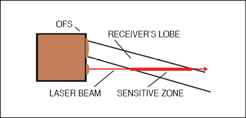
In a typical OFS, a narrow beam of a red laser light (eye-safe laser) comes out of an opening on the front. A detector behind a lens in another window is sensitive to incoming laser light in a narrow lobe that overlaps the transmitter beam. If there are fog particles in the overlap zone, light is scattered back and a signal is induced on the sensor’s raw signal output.
The raw signal output is an analogue voltage and a measure of the amount of backscattered light from the overlap (sensitive) zone. So the more fog in the overlap zone, the stronger the signal.
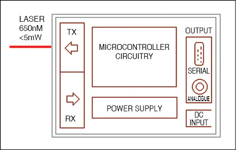
Density of fog, which is the function of visibility, can be measured within a controlled environment using an OFS as outlined above. Here, signal analysis/processing is done in an integrated microcontroller (MCU). The primary signal is first sampled for a finite duration and then calculated according to a derived formula, to convert measured signal into visibility.
Calculated visibility is presented in digital form (as an ASCII string) on the serial (RS232) output of the OFS. The MCU also controls the analogue output, indicating visibility directly. This analogue output, like digital output, is also updated at regular intervals.
In practice, light sender and receiver optics are heated up to (slightly above) the ambient-temperature level using a heating wire (anti-dew heater) mounted around these. This is done to ensure that no water droplets form, thus no further (undesired) losses are incurred due to absorption and refraction of the transmitted light beam.
Besides, in order to keep electronics dry, a membrane ventilator is used that keeps the pressure inside at the same level as outside. This prevents liquid (water) from getting sucked into the sensor through microcracks at a falling temperature.
Applications
It is well-known that fog causes many accidents. An OFS will work well for road safety and a lot of other applications. The sensor is sensitive to particles in a limited zone ahead of the location of the sensor that limits the visibility in the air.
These particles are normally microscopic water particles constituting fog, but these could also be snowflakes, raindrops or air pollutants. However, main indications of low visibility are fog or snow.
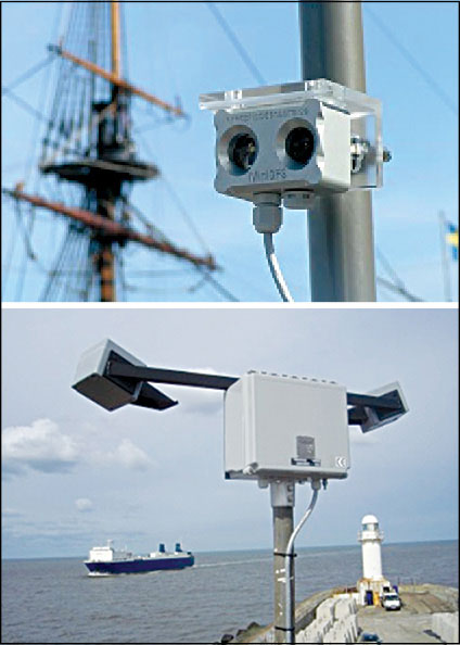
Exterior scene. Road keepers often install OFSes because they need information about the weather-associated factor that has a high impact on road safety, which is visibility. This vital information is needed for optimising road maintenance and for making decisions regarding speed limits using variable signs.
OFSes, measuring atmospheric visibility (meteorological optical range) by determining the amount of light scattered by particles in the air, are widely used in ports and harbours.
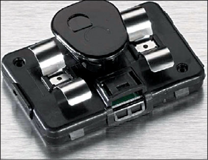
Interior role. How would you know if you are maintaining a safe distance from vehicles around you when headlights cannot penetrate fog? The new class of compact, sensitive and reliable interior OFSes could come in handy.
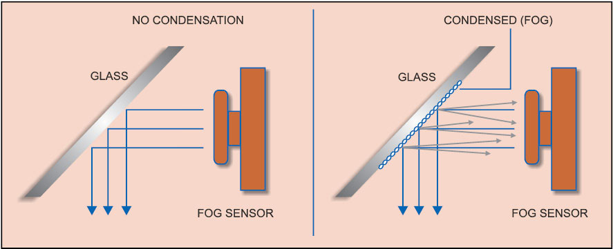
The windshield-mountable interior OFS provides an output signal that corresponds to the level of moisture on the interior glass surface of the vehicle.
Note that, unlike the common (exterior) OFS, the interior fog sensor works by transmitting a beam of infrared light onto the interior glass. When fog is present, the beam is scattered back to the sensor. This information is then used by the vehicle’s climate control system to determine if the defogger or glass-heating elements should be activated.
The fog sensor’s high sensitivity allows fog to be detected by the sensor before it is detected by the human eye. This not only improves driving safety but also the occupants’ comfort and convenience. For instance, if a vehicle can decipher that it is foggy outside, it can automatically switch on fog lamps or emergency flashers, helping the driver see, along with helping other motorists notice the occupied vehicle.
In short, OFSes are suitable for a vast range of applications including, but not limited to:
1. Providing automatic control of fog sirens, navigation and warning lights
2. Weather forecasting. These could be installed on ocean-going data buoys, providing real-time fog and visibility data
3. Integrating into existing systems for synoptic weather observations
Hitting the mark
In order to get the best from an OFS (exterior or interior), you must do your home work well. The exterior sensor should be mounted such that it looks horizontal and there must not be anything in the sightline closer than 5m to 10m. A simple shield protecting the sensor from direct sunlight and lenses from rain, reaching not more than 100mm in the laser beam direction, helps keep away precipitation from the optics. But in most cases, the existing small shield on the sensor front is sufficient.
When mounting an interior sensor (on the windshield), try and limit the overall distance between the glass and the sensor in the range of 4cm to 10cm. The best mounting position for this sensor is between the windshield and the rear-view mirror.
For DIYs
With the help of a ready-made exterior or interior OFS, you can build your own fog-related projects for your home, office and vehicle. Working voltage of an optical fog detector is between 6V DC and 16V DC, with a current requirement in the range of 60mA to 600 mA (refer official datasheet of your OFS).
If you want to study the atmospheric visibility of fog and its constituents, or if you want to fabricate a smart fog-triggered warning system for automobiles, an external MCU circuitry and a few lines of software are required to process output signals (serial data or analogue voltage) available from the OFS.
For basic projects, string output from the OFS can be routed to a logger with RS232 input or to a PC via the serial port and with a terminal program like Hyper Terminal.


Hi!
How much would this fog sensor cost approximately?
i dont think it would be much, maybe as little as $20/sensor. But this current proposal would not be sensitive enough to be effective. Physics of light don’t lie.