Dense wavelength division multiplexing (DWDM) is a promising transmission technology that can offer very high bandwidth capabilities in the range of terahertz. Such capabilities are possible due to transmission of a large number of high-speed channels simultaneously.
The rapid growth of information technology has led to new services hungry for transmission capacity. Services such as voice-over-Internet protocol (VoIP), video streaming, telemedicine, telecommuting, broadcasting of TV programmes, high-speed file sharing, user-generated video, online video gaming, online education and shopping need a transmission medium with very high bandwidth capabilities for handling the vast amounts of information. Fibre-optics, with its comparatively infinite bandwidth and employing the latest multiplexing techniques, has proven to be the solution.
Multiplexing techniques
Information transfer from one place to another takes place through different types of media such as copper lines, fibre-optic cables and space. To exploit maximum information-carrying capabilities of these transmission media, several information channels are simultaneously sent over the common transmission medium. This technique is known as multiplexing.
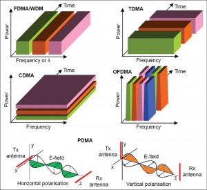
In time-division multiplex access (TDMA), time on the transmission medium is shared amongst multiple data sources, that is, all signals operate with the same frequency at different times. It is a digital technique that divides a single channel or band into time slots (Fig. 1). Each time slot is used to transmit one byte or another digital segment of each signal in sequential serial data format. An example of TDMA-based technology is the basic global system for mobile communications (GSM).
A variant of TDMA, known as statistical/asynchronous/intelligent TDMA, dynamically allocates the time slots, on demand, to separate input channels, thus saving the channel capacity. In case of statistical TDMA, the data in each slot must have an address part which identifies the source of data.
In frequency division multiplex access (FDMA), all signals operate at the same time with different frequencies. Thus, it is a process of dividing one channel or bandwidth into multiple individual bands, each for use by a single user (Fig. 1). The information to be transmitted is modulated on to each subcarrier, and all this is linearly mixed together. The best example of FDMA-based system is the cable television system.
Orthogonal frequency-division multiplexing (OFDM)—a variant of FDM with more efficient spectral efficiency—distributes the data over a large number of carriers that are closely spaced at precise frequencies (until they are actually overlapping). This is done by finding frequencies that are orthogonal, which means that they are perpendicular in a mathematical sense, allowing the spectrum of each sub-channel to overlap another without interfering (Fig. 1). Worldwide interoperability for microwave access (WiMAX) and long-term evolution (LTE) cellular systems are good examples using OFDM.
Code-division multiple access (CDMA) is a radio technology in which a spread spectrum signal is generated by modulating the radio frequency (RF) signal with a code comprising different pseudorandom binary sequences for each user, which is inherently resistant to a noisy signal environment.
A number of spread spectrum RF signals thus generated share the same frequency spectrum. Thus the entire bandwidth available in the band is used by each of the users using the same frequency at the same time (Fig. 1). It is a pure digital technology in which information is digitised, compressed and processed in a logic circuit with a higher frequency coded chipping signal.
The chipping signal is derived from a pseudorandom code generator that assigns a unique code to each user of the channel. This code spreads the information signal over a wide bandwidth. The resulting signal is at a low power level and appears more like noise. Many such signals can occupy the same channel simultaneously. The third generation (3G) cell phone technology called wideband CDMA (WCDMA) uses a similar method.
Polarisation division multiple access (PDMA) separates signals by the use of different polarisations (horizontal and vertical) of the antennae. Thus, two different signals can use the same frequency without causing any interference, one transmitting a vertically polarised signal and the other transmitting a horizontally polarised signal (Fig. 1). Satellite systems use PDMA scheme.
In fibre-optic system, dual polarisation-quadrature phase shift keying (DP-QPSK) is used for multiplexing, which results in very high data rates over a single optical fibre cable. For this purpose, high-speed data is divided into two slower data streams—one using vertical light polarisation and the other using horizontal light polarisation.
Wavelength division multiplexing (WDM) is conceptually the same as the FDM, except that it involves light signals transmitted through fibre-optic channels in order to cater to the high information-carrying capacity of fibre optic cables (Fig. 1). Very narrow bands of light signals from different sources are combined to make a wider band of light.
Evolution of transmission capacity
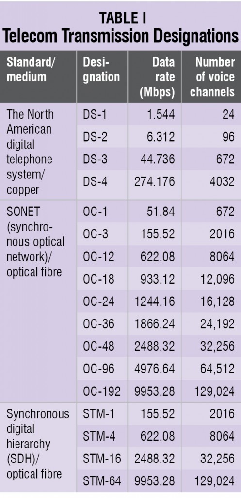
Multiplexing of several low data rate channels is done in order to utilise the high data rate transmission capacity of transmission media. Such a system, known as the North American digital telephone system/hierarchy, was developed in the early days of telecommunication for sending several telephone signals over a common transmission medium such as copper line. The system uses pulse-code modulation (PCM) in conjunction with TDM.
The basic digital multiplexing standard established in the United States is called the Bell System Level 1 PCM Standard or the Bell T1 Standard. This standard is used for multiplexing 24 separate voice channels together. As a standard voice telephone signal has a bandwidth of 4kHz, it is sampled at twice the 4kHz frequency, that is, at 8kHz (Nyquist rate).
Each sample is then converted to an 8-bit binary number. This occurs 8000 times per second. Thus, if we multiply 8k samples per second × 8 bits per sample = 64kbps, we get the standard bit rate for a single voice channel in the North American DS1 System, which is 64kbps. Each 64kbps voice channel is designated as digital signalling level 0 or DS-0. Each frame in the 24-channel multiplexer comprises 8 bits per channel × 24 channels + 1 framing bit = 193 bits.
The total data rate when transmitting 24 channels is determined by 193 bits per frame × 8000 frames per second = 1.544Mbps = T1 or DS-1 designation (Table I). If four T1 lines are multiplexed together, we get 4 × 24 channels = 96 channels = 6.312Mbps = T2 or DS-2 designation. Multiplexing seven T2 lines together, we get 7 × 96 = 672 channels = 44.736Mbps = T3 or DS-3 designation. If six T3 lines are multiplexed together, we get 6 × 672 = 4032 channels = 274.176Mbps = T4 or DS-4 designation. Such multiplexed signals over copper lines can reach up to 1-2km only due to signal attenuation.
Exploiting the transmission carrying capability of optic fibre, another standard, known as synchronous optical network (SONET), with designations ranging from OC-1 to OC-192 has been developed (Table I). These optical signals can be transmitted over distances up to 100km without the need of repeaters.
In order to meet the demand for higher bit rates, a digital multiplex hierarchy called the plesiochronous digital hierarchy (PDH) evolved in various parts of the world, differing with one another. These PDHs developed and adopted by Europe, North America and Japan used different tributaries for multiplexing and de-multiplexing. Thus, these imposed compatibility and interoperability issues.
In order to overcome issues with PDH systems, a synchronous digital hierarchy (SDH) system has been developed in which each rate is an exact multiple of the lower rate. SDH is a transport hierarchy based on multiples of 155.52Mbps. The basic unit of SDH is synchronous transmission module level-1 (STM-1) (Table I). Transmission rates of up to 40Gbps can be achieved in modern SDH systems.
Even though OC-192 is the maximum data rate specified by SONET, recent developments in SDH technology allow for transmission as high as 40Gbps.
The existing SONET/SDH network architecture is best suited for voice traffic rather than today’s high-speed data traffic. To upgrade the system to handle this kind of traffic is very expensive and hence the need for the development of an intelligent all-optical network is aroused.
The solution is to use frequency multiplexing at the optical level or wavelength division multiplexing (WDM/DWDM). Here, the basic idea is to use different optical carriers or colours to transmit different signals in the same fibre.
To understand WDM transmission, let us consider a highway analogy where one fibre can be thought of as a multi-lane highway. Traditional TDM systems use a single lane of this highway and increase capacity by moving faster on this lane. Optical networking utilising DWDM is analogous to accessing the unused lanes on the highway to gain access to an incredible amount of untapped capacity in the fibre.
An additional benefit of optical networking is that the highway is blind to the type of traffic that travels on it. Consequently, the vehicles on the highway can carry asynchronous transfer mode (ATM) packets, SDH and IP.
Such a network will bring intelligence and scalability to the optical domain by combining the intelligence and functional capability of SONET/SDH, the tremendous bandwidth of DWDM and innovative networking software to spawn a variety of optical transport, switching and management-related products. This, coupled with the availability of 32-channel and 96-channel WDM, has led to the development of systems capable of 320Gbps to 1.2 terabit-per-second transmission.
Evolution of DWDM
Early WDM began in the late 1980s using the two widely spaced wavelengths in the 1310nm and 1550nm (or 850nm and 1310nm) regions, sometimes called wideband WDM.
The early 1990s saw a second generation of WDM, sometimes called narrowband WDM, in which two to eight channels were used. These channels were spaced at an interval of about 400GHz in the 1550nm window. Traditional passive WDM systems were widespread with 2-, 4-, 8-, 12- and 16-channel counts. This technique usually has a distance limitation of less than 100km, without any repeater stage. Another variant of WDM, known as coarse WDM (CWDM), typically used 20nm spacing of up to 18 channels that could reach a target distance up to about 50km on single-mode fibres.
By the mid-1990s, dense WDM (DWDM) systems were emerging with 16 to 40 channels and spacing from 100GHz to 200GHz. By the late 1990s, DWDM systems were capable of 64 to 160 parallel channels, densely packed at 50GHz or even 25GHz intervals at distances of several thousand kilometres with amplification and regeneration along the route.
Interestingly, in a WDM network, the vast optical bandwidth of a fibre (approximately 30THz) is carved up into wavelength channels, each of which carries a data stream individually. The multiple channels of information (each having a different carrier wavelength) are transmitted simultaneously over a single fibre (Fig. 2).
The reason why this can be done is that optical beams with different wavelengths propagate without interfering with one another. When the number of wavelength channels is above 20 in a WDM system, it is generally referred to as dense WDM or DWDM.
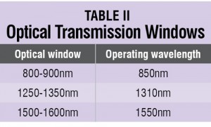
Optical fibre transmission uses wavelengths that are in the near-infrared portion of the spectrum, just above the visible and thus undetectable to the unaided eye. There are ranges of wavelengths known as transmission windows at which the fibre operates best (Table II).
These wavelengths best match the transmission properties of available light sources with the transmission qualities of optical fibre. Usually, LEDs are used for 850nm or 1310nm multimode applications and lasers are used for 1310nm or 1550nm single-mode applications.
For DWDM system, 1550nm window has been chosen due to low-attenuation characteristics of glass at 1550nm and the fact that erbium-doped fibre amplifiers (EDFAs) operate in the 1530nm-1570nm range. The International Telecommunications Union (ITU) defines a frequency grid that specifies standard frequency spacing as 100GHz, which translates into a 0.8nm wavelength spacing.
DWDM system components
Transmitter and receiver. A transmit transponder is used at transmitter’s side to change electrical signals into ITU grid-specific optical wavelengths. For this purpose, it employs a narrow band of laser to generate optical pulses. At the receiver’s side, a receive transponder converts optical pulses to electrical signal, if required. In these systems, small form-factor pluggable (SFP) transceivers are used to interface the system with the fibre-optic cable.
Transmission media. Due to minimum fibre-optical attenuation at 1550nm and availability of optical amplifiers in 1550nm region, most of the DWDM systems operate in C-band, that is, from 1530nm to 1565nm. In this range, conventional single-mode optical fibres (ITU G.652 compliant) undergo high dispersion, which severely limits the distance between repeater stations. Solutions lie in the use of dispersion compensating fibre (DCF) and zero dispersion fibre (ITU G.653 compliant).
But, DCF adds additional power loss and zero dispersion fibre results in nonlinearity such as four-wave mixing (FWM). A fibre that has small but non-zero amount of dispersion can minimise the non-linearity effects. The ITU G.655 compliant, non-zero dispersion fibre (NZDF) has dispersion which is carefully chosen to be small enough to enable high-speed transmission over long distances, but large enough to suppress FWM. So, ITU G.652 is preferred for access network and ITU G.655 for backbone network. In summary, a future-proof fibre-optic DWDM network should have a combination of ITU G.652 and G.655 fibres.
WDM MUX and DMUX. Wavelength division multiplexer/de-multiplexer combines/separates discrete signals transmitted at different wavelengths. Essentially, the multiplexer is a mixer and the de-multiplexer is a wavelength filter.
Wavelength-division de-multiplexers use several methods (bulk optical diffraction gratings or interference filters for spacing between 1nm and 2nm or fibre Bragg gratings (FBGs) for spacing less than 0.8nm) to separate different wavelengths depending on the spacing between the wavelengths. FBGs are of critical importance in DWDM systems in which multiple closely-spaced wavelengths require separation.
Light entering the FBG is diffracted by the induced period variations in the index of refraction. By spacing the periodic variations at multiples of the half-wavelength of the desired signal, each variation reflects light with a 360-degree phase shift, causing a constructive interference of a very specific wavelength while allowing others to pass.
Optical amplifier. In DWDM system, a pre-amplifier is used to boost the signal pulses at the receiver’s side and a post-amplifier boosts signal at the transmitter’s side. In-line amplifiers are placed at different points (usually every 50-60km) from the source to provide recovery of the signal before it is degraded significantly. EDFA is the most popular optical amplifier used to boost the signal level in the 1530nm to 1570nm region of the spectrum.
Most importantly, EDFAs allow signals to be regenerated without having to be converted back to electrical signals. In this amplifier, an external laser source of either 980nm or 1480nm is used to pump it and considerably high amplification of the order of 30dB is achieved.
Regenerator. If the length to be bridged is too long to be covered, regenerators are employed. These regenerators perform real 3R functions—reshaping, retiming and amplification of the signal. Therefore the signals have to be de-multiplexed, electrically regenerated and multiplexed again.
Optical add/drop multiplexer. In a DWDM system, optical add/drop multiplexer is used to add or drop some specific wavelengths from the already multiplexed optical signal. Such add/drop multiplexer may use complete de-multiplexing or other techniques. A fibre-optic circulator employing FBG may be used to drop any specific wavelength and pass the others.
DWDM system
DWDM is an optical multiplexing technology that allows many discrete transport channels, by combining and transmitting multiple signals simultaneously at different wavelengths, on the same fibre. In effect, one fibre is transformed into multiple virtual fibres. So, if you were to multiplex 32 STM-16 signals into one fibre, you would increase the carrying capacity of that fibre from 2.5Gbps to 80Gbps.
Because of DWDM, single fibres have been able to transmit data at speeds up to 400Gbps. A key advantage to DWDM is that it is protocol and bit-rate independent. DWDM-based networks can carry different types of traffic at different speeds over an optical channel, and so can transmit data in SDH, IP, ATM and Ethernet.
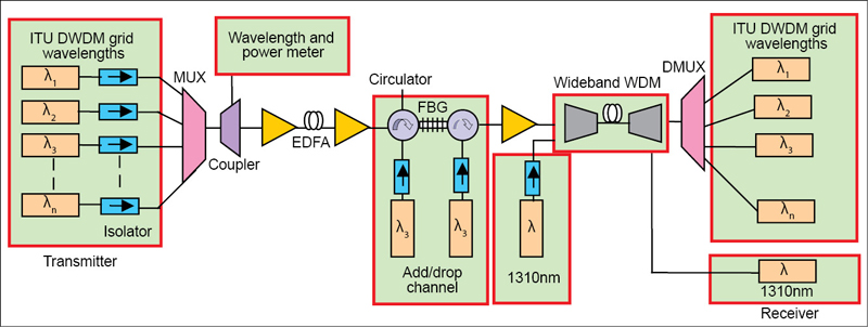
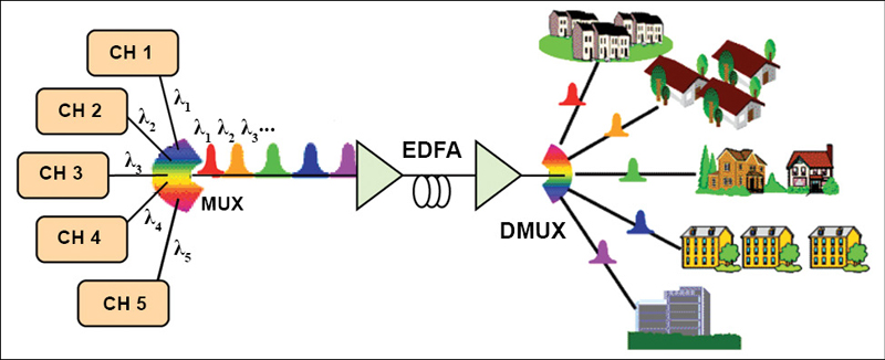
Such a DWDM system is shown in Fig. 3 where DWDM and EDFA is used to transmit several channels of high-bandwidth information over a single fibre. These signals are converted into corresponding wavelengths of light in accordance with the ITU grid and are multiplexed with the help of multichannel coupler or wavelength division multiplexer.
In order to minimise back reflections, an optical isolator is used with each optical source. Multiplexed optical signal is then routed through a single optical fibre cable. After covering a distance of 50-100km, the signal needs to be amplified. So, several stages of amplification using EDFA are required in order to cover long distances.
In order to add or drop some channels, an optical circulator in conjunction with FBG is used. After amplification, a wideband wavelength division multiplexer is used to combine 1310nm signal with the 1550nm window signals. At the receiver’s side, 1310nm signal is extracted via another wideband wavelength division de-multiplexer.
Finally, a dense wavelength division de-multiplexer that is made of an array of FBGs, each tuned to specific transmission wavelength, separates all the 1550nm window signals. A tap coupler is used to couple some amount of optical power for wavelength and power measurement.
Conclusion
The growth of the fibre-optics industry, including the advances in optical sources and detectors that operate in the 1550nm range, the developments of EDFAs, FBG and mutli-channel DWDM systems, has been explosive over the past five years. Presently, DWDM is one of the hottest emerging market segments in global telecommunications to usher in the next generation of services.
The author, currently with Bharat Sanchar Nigam Limited, is a recipient of senior research fellowship of UGC. His research interests include wired and wireless technologies for high-speed internet access


