


Hybrid power devices are combinations of different power technologies. Hybrid power plants often contain a renewable energy component such as photovoltaic (PV) that is combined with wind power, thermoelectric power, solar thermal power, or a system like battery storage or solar thermal storage. Thermoelectric generators are semiconductor devices that have no moving parts and convert heat directly into electricity. When combined with thermal storage they can provide electricity round the clock at as low as $0.06 per kilowatt-hour and could achieve 16% efficiency.
PV cells convert the UV and visible regions of the solar spectrum while the thermoelectric modules use the infrared region to produce electrical energy. Thus, combining both these systems in a hybrid system provides enhanced performance. While PV panels convert up to 20% of solar energy into electricity, the solar thermal collectors capitalise on the untapped heat energy of the PV system, thereby increasing the energy production efficiency while occupying less space

Global energy demand is likely to increase by 48% in the next 20 years due to population explosion. Currently 80% of energy needs are met by fossil fuels, which emit greenhouse gases that lead to global warming and climate change. Their negative environmental impact is leading to development of renewable energy sources like solar, geothermal, and hydro.
Sun is an eternal source of renewable energy outputting 3.8×10²⁰ megawatts (MW) of which our Earth receives about 1.7×10¹⁴ kilowatts (kW)—only a tiny fraction of the total radiation. However, 84 minutes of this tiny solar radiation is enough to meet our world’s energy demand for one year (about 900EJ). India receives solar energy of 5 to 7 kilowatt-hours per metre square (kWh/m2) for 300 to 330 days in a year, which is sufficient to install 20MW solar power plants per square kilometre land mass.
Solar energy can be utilised to heat fluids or to generate electricity. However, at present only 2% of world’s energy comes from Sun, as solar energy harvesting has been expensive and its efficiency is low. New technological advances like improved solar cells, hybrid photovoltaic and thermoelectric generators, use of aerogel, and cogeneration of electricity from solar cells as well as solar heating for thermal power generation is leading to decreasing cost and increasing efficiency, which is now leading to a quantum jump in solar energy usage.
Photovoltaics
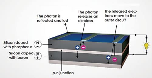
A photovoltaic cell is made of semiconductor materials that absorb photons of the sunlight and generate a flow of electrons. Photons are elementary particles generated by Sun that carry solar radiation at a speed of 300,000km/s. When the photons strike a semiconductor material like silicon, they release the electrons from its atoms, leaving behind a vacant space called ‘hole.’ The stray electrons move around looking for a hole to fill.
Generally, a PV cell is made up of two types of silicon. The silicon wafer that is exposed to the Sun is doped with atoms of phosphorus, which has one more electron than silicon. The back side of the cell is made of silicon doped with atoms of boron, which has one less electron than silicon.
The sandwich thus constructed works like a battery. The layer that has surplus electrons becomes the negative terminal (n) and the other side that has a deficit of electrons acts as the positive terminal (p). An electric field is created between the two layers at the junction.
On excitation by photons electrons are swept to the n-side by the electric field at the junction, while the holes drift to the p-side. Both the sides are provided with metallic electrical contacts to collect electrons and holes. Electrons then flow in the external circuit in the form of electrical energy. Fig. 1 shows how a PV cell works.
Thermoelectricity
Thermoelectricity, as the name suggests, stands for the conversion of thermal energy (temperature difference) into electricity. It encompasses mainly two phenomena: the Seebeck effect and Peltier effect.
Seebeck effect is the phenomenon that a potential difference will appear between the two ends of a metal or semiconductor wire when they are kept at different temperatures. The potential difference is proportional to the temperature difference and the material’s property known as Seebeck coefficient.
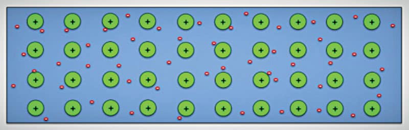
All materials are made of atoms, and atoms contain positively charged nucleus with negatively charged electrons moving around them. The electrons that are closer to the nucleus are bound more strongly, whereas the outer ones are loosely bound. When the temperature is uniform, the distribution of negative electrons is uniform and neutralises positive ions everywhere in the material, as shown in Fig. 2.
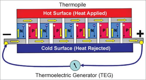
But when one end of the wire is heated and the other end is kept cool, electrons at the hot end gain more energy and higher speed than those at the cool end, which is indicated by the longer arrows in Fig. 3. So, at any instant more electrons move to the cold end than those moving back. So, the hot end becomes positively charged and the cold end becomes negatively charged, and current flows through the external conductor of a thermoelectric generator (TEG).

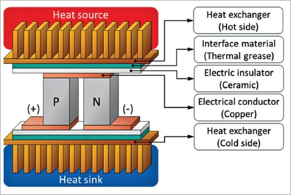
A single thermoelectric device is constructed from two solid-state devices that are usually made from bismuth telluride (Bi2Te3), as shown in Fig. 4. One of these pellets of semiconductor is doped with acceptor impurity to create a p-type component to have more positive charged carriers or holes, thus providing a positive Seebeck coefficient. The other is doped with donor impurity to produce an n-type component to have more negative charged carriers, thus providing a negative type of Seebeck coefficient. The two semiconductor components are then physically connected serially on one side, usually with a copper strip, and mounted between two ceramic outer plates that provide electric isolation and structural integrity.
The Seebeck effect is a direct energy conversion of heat into a voltage potential. It occurs due to the movement of charge carriers within the semiconductor. Charge carriers diffuse away from the hot side of the semiconductor. This diffusion leads to a build-up of charge carriers at one end. This build-up of charge creates a voltage potential that is directly proportional to the temperature difference across the semiconductor.
The power generated in a TEG is single-phase DC that equals I2RL, where I is the current and RL is the load resistance. The output voltage and output power are increased either by increasing the temperature difference between the hot and cold ends or by connecting several TEGs in series, as shown in Fig. 5.
The current flows as long as heat is applied to the hot junction. The process is reversible. If the hot and cold junctions are interchanged, the valence electrons flow in opposite direction and direction of the current changes. The thermoelectric effect allows converting waste heat into electric power.
By combining thermoelectric and PV effects, higher solar electricity conversion efficiency is possible. PV absorbs about 58% of solar energy between 200nm and 800nm wavelengths. The rest of the solar energy from 800nm to 2500nm cannot be converted to electricity by PV. But this spectrum of solar radiation can generate electricity through thermoelectric effect by heating TEG.
Thermoelectric figure-of-merit
The performance of thermoelectric materials is defined by unitless figure-of-merit as given below:
ZT=σS²T/k
where ZT is the thermoelectric figure-of-merit while σ, S, k, and T are electrical conductivity, the Seebeck coefficient, the thermal conductivity, and the absolute temperature, respectively.
The Seebeck coefficient of a material is the induced thermoelectric voltage per Kelvin generated in response to a temperature difference across the material, as induced by the Seebeck effect. It is often given in microvolts per Kelvin. The Seebeck coefficient depends on factors like temperature, work functions of the two TE materials, electron densities of the two components, and scattering mechanism with each solid. Performance of a TEG is determined by the Seebeck coefficient of the pair of materials forming the TEG.
Table 1
Seebeck Coefficient of Some Common Thermoelectric Material in µV/K |
|||||
| Bismuth | Constantan | Germanium | Silicon | Tellurium | Selenium |
| -72 | -35 | 330 | 440 | 500 | 900 |
Table 1 gives the Seebeck coefficient of some standard TE material in microvolt/K at 0°C. An ideal TE material would have a Seebeck coefficient of more than 200µV/K for best voltage-generating ability.
Peltier Effect
In a circuit, when DC current flows through two dissimilar material, say copper and bismuth, the junction where the current passes from copper to bismuth would be hot and the junction where current passes from bismuth to copper would be cold. This effect, known as Peltier effect, is used to build devices like Peltier heater, solid-state refrigerator, and heat pump.
A good thermoelectric material should have following qualities:
- Its Seebeck coefficient should be as high as possible. It is important to maximise energy conversion. The open circuit voltage generated by a TEG is proportional to the Seebeck coefficient and temperature difference across the TEG. Hence high Seebeck coefficient leads to a high voltage.
- To minimise thermal loss through the thermoelectric material and to have large temperature difference across the TEG, thermal conductivity of the TE material should be as low as possible.
- Its electrical conductivity should be as high as possible for reducing internal Joule heating losses of the thermoelectric elements.
A TEG’s efficiency depends very much on the operating temperature difference between the junctions. The bigger the temperature difference, the more efficient the TEG.
There are three main types of thermoelectric materials used in thermoelectric generators:
- Bismuth telluride (Bi2Te3) alloy: It is a semiconductor that has high electrical conductivity but is not good at transferring heat. The best working temperature of this class of material is below 450°C. Bismuth telluride materials with high figure of merit (ZT) and TEG modules, as shown in Fig. 6, have high conversion efficiency of more than 8% over temperatures of 25°C to 250°C and are widely utilised in energy generation and refrigeration.

Fig. 6: Conversion efficiency of improved BiTe material With improved techniques, p-type BiTe TE material that has average ZT of 1.08 and n-type BiTe with 0.84 ZT has been made. The significant enhancement in ZT could be achieved through compositional and defect engineering.
Type I module is constructed using p-type Bi0.5Sb1.5Te3 and n-type using Bi2Te2.7Se0.3S0.01. Type II material is constructed from p-type Bi0.4Sb1.6Te3 and n-type Bi2Te2.7Se0.3S0.01Cu0.01 materials. Fig. 7 and Fig. 8 show the Seebeck coefficient and figure of merit of these two types of improved BiTe materials, respectively.
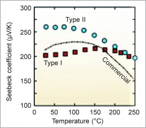
Fig. 7: Seebeck coefficient of improved Type I and Type II BiTe material - Lead telluride (PbTe) alloy: Low conversion efficiency is a big obstacle that impedes large scale application of TE materials for power generation. Lead telluride alloy is recognised as an excellent compound for power generation in the mid temperature range of 500-800°K. It has highly symmetric rock salt crystal structure, which is chemically and thermally stable. Lead telluride can be made either a p-type or n-type semiconductor.
Fig. 8: Figure of merit of improved BiTe material The last decade has witnessed a quantum jump in TE properties of PbTe. Its maximum figure of merit (ZT) has already crossed 2. It has a unique combination of high power factor and significantly lower thermal conductivity, high Seebeck coefficient, and high electrical conductivity. Fig. 9 shows Seebeck coefficient and figure of merit of PbTe materials recently developed. It has a drawback that it is highly toxic in nature. Commercial PbTe material has about 7% conversion efficiency with ZT about 1.0.
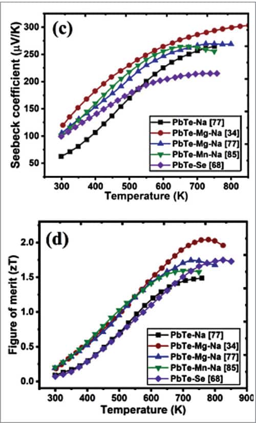
Fig. 9: Seebeck coefficient and ZT of lead telluride TE material Recently researchers have enhanced the ZT of a sintered material to 1.8 (600°C) using a nanostructure forming technology. Further, an electrode material has been developed that contacts very well electrically and thermally with PbTe containing MgTe nanostructures, achieving a conversion efficiency of about 11% with hot side at 600°C and the cold side at 10°C.
This breakthrough has made the way to convert waste heat and solar thermal power to large scale practical application. Because the nanostructures formed in the PbTe sintered material effectively scatter heat carrying phonons, but have no effect on the charge carrier transport, there is dramatic improvement in the ZT.
- Silicon-germanium alloy: It is a kind of semiconductor that is often used for thermoelectricity generation with a working temperature around 1300°C. Combining Si and Ge allows to retain high electrical conductivity of both components and reduce the thermal conductivity due to the increased phonon scattering as Si and Ge have different lattice properties. Due to this reason Si-Ge alloys are currently the best TE material for high temperature application.
Conventional Si-Ge materials have ZT values of 0.9 and 0.5 at 1200K for n-type and p-type materials, respectively. By adopting nanocomposite approach reducing the grain size to around 5nm, ZT values can be increased by a factor of two and conversion efficiency can also be increased considerably. Ge is a scarce material and hence this alloy is costly. However, using only 5% of Ge it is possible to have Si-Ge alloy with improved performance.
The advantage of the newly developed nanocomposites is that its ZT values consistently remain above 1 over high temperature range between 600°C and 1000°C. Hence, these are the best TE materials for high temperature application for power generation by solar radiation, radioisotope devices, and waste heat recovery system. Table 2 shows the ZT values of bulk and improved nanostructured Si-Ge TE materials.
A thermoelectric device with a ZT of 1.25 will have an efficiency of about 10%. A segmented Si-Ge TE device over temperature range of 300K to 1300K will have an efficiency of about 12.1%.
Block diagram of a typical thermoelctric power harvesting system is shown in Fig. 10.
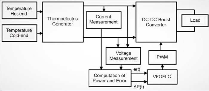
A thermoelectric power generation system has low energy conversion efficiency. According to the principle of maximum power transfer, the system would transfer the maximum power when the load resistance is equal to the internal resistance of the TEG. Based on this principle, several maximum power point tracking (MPPT) algorithms may be selected with different control logic to harvest the maximum power from the TEG. If a TEG is connected directly to the load, the load impedance will set the operating point which might result in the TEG output being less than the maximum output power.
The MPPT technique is considered an efficient mechanism to improve the performance of TEG by increasing the conversion efficiency. In this system, the operating point of the TEG is moved promptly towards an optimal point to increase energy harvesting by using a variable fractional order fuzzy logic controller (VFOFLC) based MPPT technique. The variable tracking step size is applied using a dynamic variable fractional factor whose value is calculated based on the voltage output of the TEG. The fraction order term introduced in the MPPT algorithm would contract or expand the input domain of the fuzzy logic controller to shorten the tracking time and maintain a steady-state output around the maximum power point.
Optimization of the TEG
It has been found that the output power is correlated with the geometry of the device. By changing the leg height and the number of thermoelectric pellets to an optimum value it is possible to maximise electric power or efficiency at given operating conditions. There is interdependence between optimal leg geometry and the electrical load resistance.
If number of legs is low, the energy conversion is low, because the load resistance (RL) is not sufficient to obtain an adequate high voltage and vice versa. A reduction of the leg length leads to a reduction of the electrical resistance, and an increase of the leg length leads to the higher temperature difference across the TEG. If the geometric parameters like leg length, number of semiconductor pellets, the base area ratio of the semiconductor columns are optimised, the output power and thermal efficiency are considerably improved.
The shape of the legs of TEG devices has considerable effect on the device performance. The conventional rectangular leg shape found in commercial TEGs is not the optimal shape for heat-to-power energy conversion. The hourglass shaped TE legs result in more than double the electrical potential and maximum power compared to conventional rectangular shape. The trapezoid leg with the largest cross-sectional area at the hot side results in about double the electrical potential and a 50% increase in the power output compared to the conventional rectangular shape. The electrical output power values, if optimised, can be 890% higher than a random value without optimisation.
Heat sink is required at the TEG when a high heat flow rate is applied on the hot side of the TEG. In order to have quick heat dissipation at the cold side cooling radiators are provided there, so that bigger temperature difference across the TEG can be obtained. The fins attached to the heat sinks are very important for enhancing the heat transfer at the hot and cold sides. The heat transfer increases when the number of fins are increased and the fin height is more, due to more heat transfer area. However, increase of heat transfer area is limited to an optimum value beyond which the change in the output electrical power becomes less significant.
The thermal resistance of the heat sink (Rhs) is:
Rhs=(Theat sink - Tamb)/Qh
where, Theat sink is the sink temperature, Tamb is the environmental temperature, and Qh is the heat flow. Experimental results show that increasing the thermal resistance of both cold and hot side heat sinks by 10% improves the electrical output power by 8%.
Aerogel
Aerogels are a class of synthetic porous materials derived from a gel, in which the liquid component has been replaced with a gas without collapsing the gel structure by freeze-drying. It can be made from silica, carbon, iron oxide, gold, copper, polymer, etc.
The final product is extremely porous (80-98% porosity) with very little solid material; up to 99.8% of the aerogel may have nothing but air. It has a typical density of about 0.001gm cm–3. Its thermal conductivity is extremely low, about 0.017W/mK, which makes the material an ideal insulator. It can be made transparent.
By reducing heat losses and simultaneously being transparent, aerogels allow a solar plant to operate at higher temperature and at higher efficiency without using any vacuum device. These advantages make an aerogel assisted solar thermal plant very economical and eliminates lot of maintenance problems.
Concentrated high-efficiency Solar Thermoelectric Generator
A solar thermoelectric generator (STEG) is a solid-state device that can convert solar energy at around 15% efficiency.
It has three sections: solar absorber, thermoelectric generator, and the thermal management system comprising insulation, heat exchangers, and vacuum/aerogel enclosure, etc.
There are no moving parts and there is no need of high-temperature operating fluids. Its robustness in harsh temperatures makes it very useful for standalone power conversion or making hybrid solar thermal power generator in conjunction with a PV system.
The efficiency of STEG depends on both the efficiency of solar absorber and on the thermoelectric efficiency of the device. There are mainly two approaches to increase the efficiency of STEG devices: increasing temperature difference between the hot and cold ends and using improved materials with ZT more than 1. Recently, several nanostructured materials have been developed that have higher ZT values suitable for STEG.
There are two routes to increase the temperature difference in a STEG: first, optical concentration of sunlight enabling to increase the heat flux at the absorber surface, and second by providing thermal concentration where the area of a highly thermally conducting absorber is greater than area of the thermoelectric legs increasing the heat flux through the legs.
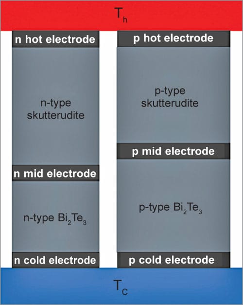
It is possible to construct a durable STEG device with more than 15% efficiency using improved material consisting of a segmented n-type leg composed of skutterudite and La1Te4 and p-type leg of skutterudite and Yb14MnSb11, and also using nanostructured Bi2Sb3 based alloys (all these three types have an effective ZT of about 1.4 to 1.6 at 800K).
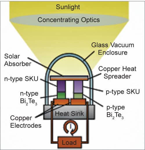
Operating temperatures across Thot-Tcold=900°C–200°C are maintained using fresnel lens to concentrate sunlight. In order to reduce heat losses from the solar collector a vacuum system is provided, which is costly. Skutterudite is a type of arsenide mineral having general formula as TPn3, where T is a transition metal like Co, Rh, or Ir, and Pn is Sb, As, or P. Typical arrangement of STEG system is shown in Fig. 11 and Fig. 12.
Another excellent way to reduce heat losses is by using high-temperature transparent aerogels for insulation instead of vacuum system, as shown in Fig. 13.
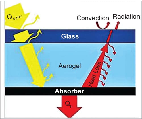
Aerogel, being transparent but an excellent insulator, allows sunlight to enter but blocks the heat from escaping from the receiver of the STEG. It offers many advantages like higher efficiency, minimises heat loss, boosts solar thermal conversion, eliminates costly vacuum system and its maintenance cost. Due to efficient thermal transport system provided by aerogels, most of the solar radiation is absorbed by the cermet composite pad attached to the thermoelectric elements.
It is desirable to thermally insulate the TE legs to suppress lateral heat leaks that degrade thermal efficiency. Encapsulation of thermoelectric legs with aerogels prolongs the life of TE devices.
The primary cause of deterioration of most thermoelectric materials is thermal decomposition or sublimation at high operating temperatures. For example, aerogel present near the surface of skutterudite material, such as CoSb3, prevents transport of Sb vapour by establishing a highly localised equilibrium Sb-vapour atmosphere at the surface of skutterudite.
Some solar absorbers are painted with black paint to increase the heat absorption and are fabricated from metal dielectric multilayer cermet composites that are capable of withstanding more than 950°C.
Photovoltaic/thermoelectric Hybrid System
Solar light and its thermal energy can provide sufficient electricity to meet the global energy demand. The range of wavelengths that photovoltaic materials generally use to convert into electricity is between 400nm and 1200nm, the ultra-violet (UV) and visible range. Excess solar radiation is wasted as heat, which decreases the efficiency of PV cells and lowers their life.
TEGs are bidirectional devices that act as heat engines, converting the excess heat into electricity through the thermoelectric effect. Thermoelectric devices utilise the IR region of sunlight to generate electricity and reduce the amount of heat that PV cells dissipate. It is possible to combine PV cells and TEGs to make a hybrid system that can generate more energy. The overall power output of this system would be the sum of the power output from the PV module and the TEG.
The hybrid systems generally follow two configurations—with or without reflective components.
With reflective arrangement the spectral splitting method splits the solar spectrum into two bands. The spectrum below the 800nm cut-off wavelength gets transmitted to the PV module and above 800nm to the TEG. This system has a reflective component called wavelength segregator or prism, where the PV module and the TEG are installed perpendicular to each other. When sunlight passes through the prism, a part of the sunlight is reflected at cut-off wavelength of approximately 800nm and is absorbed by the solar cell. The radiation that is longer than the cut-off wavelength—above 800nm—is reflected to the TEG, as shown in Fig. 14.
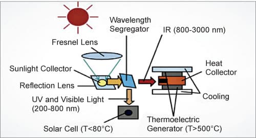
The PV module and the TEG convert solar energy into electricity independently. A cooling system is installed on the TEG to maintain the temperature difference. A concentrator increases the light intensity and hence PV modules of reduced surface area can be installed, which results in a reduced installation and maintenance cost. The spectrum splitter allows for low operating temperature and hence maximising the conversion efficiency.
Thermoelectric legs have different values of ZT at different temperatures. Hence the TE material selected depends on the operating temperature. Generally, bismuth telluride is used under 500K, lead telluride between 500-900K, and germanium silicon above 900K operating temperatures.
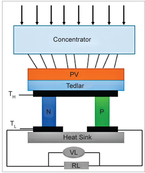
In configurations without reflective component the PV module is placed as upper component and TEG device as lower component, as shown in Fig. 15. When sunlight falls on it, the PV device absorbs the UV and visible light and rest of the solar spectrum passes through the PV module to the underlying TEG. The IR radiation heats up the TEG top side creating a temperature difference with the cold side. The solar module is coated with tedlar PVF film that offers the best protection against UV, thermal, moisture, chemical and mechanical stress.
Combination of PV and TE generators can make a very efficient device for solar energy utilisation. A PV/TE hybrid system with high concentration ratio and using multijunction PV and Bi2Te3 thermoelectric legs has conversion efficiency of about 32%. The direct electrical contribution of the TEG to the hybrid system’s efficiency is enhanced by increasing the Sun’s concentration by about 300 times. Even higher efficiency and power values can be achieved by using more advanced PV devices and improved TE materials, with a potential to reach 50% total efficiency.
Hybrid PV and Solar Thermal System
A technique that combines PV and solar thermal systems to efficiently convert solar radiation to electricity for immediate use and store the remaining inexpensive thermal energy (not utilised by PV) to convert to electricity on demand has been developed recently. It is called hybrid electric and thermal solar (HEATS) system. The prototype performs at 26.8% (with a potential to achieve 35.2%) solar to electricity efficiency and 81% dispatchability of electrical energy from thermal energy at an operating temperature of 775K using silicon PV cell (gallium arsenide PV cell can also be used).
HEATS contains a PV module as well as a thermal absorber to utilise the best of both. In this system photons in the PV band are directed to the PV cells whereas these are most efficiently converted into electricity. Low-energy photons (long wavelengths) that cannot be converted by PV cells and high-energy photons (short wavelengths), which would be converted inefficiently, are directed to the thermal absorber instead of being wasted.
This technique improves overall system efficiency and provides additional thermal energy, which can be stored at low cost to be used for electricity generation or for heating on demand. Dispatchability is the ratio of electricity generated from heat engine and total electricity generated by both heat engine and the PV modules. The arrangement of HEATS is shown in Fig. 16.
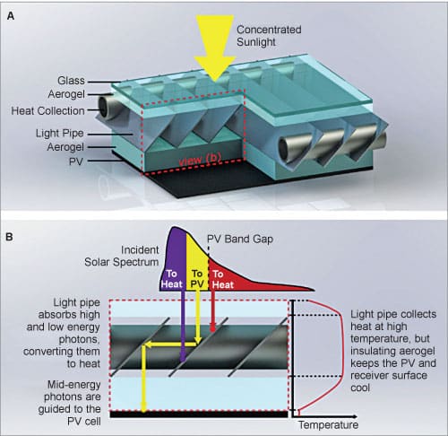
Fig. 16(A) shows the receiver concept with a cutaway section to show its internal structure. The HEATS receiver is used in conjunction with a solar concentrator, like a parabolic trough or a linear Fresnel reflector, to increase the intensity of solar radiation. The stacked structure consists of a glass protective cover, a thermally insulating transparent aerogel layer, the spectrally selective light pipe (SSLP), followed by another insulating transparent aerogel layer, and finally the PV module.
The SSLP structure consists of a series of parallel fins attached to the heat collection pipes carrying a heat transfer fluid like Therminol VP-1, which collects the thermal energy absorbed by the SSLP. The SSLP structure is formed from parallel fins made of a thermally conductive copper sheet substrate coated with a spectrally selective material in multilayers.
The SSLP absorbs high and low energy photons as thermal energy, while directing the mid energy photons to the PV module down below as shown in Fig. 16(B). Transparnt aerogel on either side allows the light to pass through but does not allow the heat to escape as it is an excellent insulator.
The aerogel layers serve to thermally insulate the SSLP from the PV module to keep the latter cool. It ensures that the SSLP can be operated at a high temperature without heat loss while the PV module and the glass cover remain at a safe low operating temperature. The transparent silica aerogels used have high solar transmittance of about 96% and low thermal conductivity of about 0.055W/m/K. As aerogels are not very strong, it is ensured that no load is transferred to it.
The advantages of hybrid PV-thermal system are mainly: (a) both solar thermal and PV cells can be housed in the same module and operated simultaneously, (b) the solar energy that would have been lost otherwise, if single PV module was used, can be recuperated usefully, and (c) the amount of energy that is generated per unit area by this tandem system is more and the payback period is less due to more energy extraction.
Rathindra Nath Biswas is a 1964-batch chemical engineering graduate from Jadavpur University, Kolkata. He was awarded a certificate for designing Benzol Plant by Giprokoks, USSR, and Certificate of Honour by Indian Institute of Metals. He has published 35 research papers in various journals. He retired from service as head – MECON, Durgapur.
