


APRIL 2012: 802.11ac, the next step for Wi-Fi 802.11, will breach the barrier of gigabit capacity. Couple this with low latency and an improved power profile and you get the next must-have feature for your gadget.

The IEEE 802.11ac standard has been developed to provide high-throughput wireless local-area network (WLAN). It promises gigabit wireless speeds to consumers.
The Initial Technical Specification Draft 0.1 was confirmed by the IEEE 802.11 Task Group ac (TGac) last year while Wi-Fi Alliance ratification is expected by the end of this year. Though the 802.11ac standard is in draft form and yet to be ratified by the Wi-Fi Alliance and IEEE, we have already begun to see products available in the market.
What is 802.11?
The IEEE 802.11 is a set of standards used for setting up WLAN between devices. The standards use 2.4, 3.6 and 5GHz frequency bands for data transmission. The most popular protocols are 802.11b and 802.11g, both of which use the 2.4GHz band. These standards use spread-spectrum and frequency-division multiplexing to control interference from microwave ovens and cordless phones.
802.11ac characteristics
WLAN 802.11ac uses a variety of new methods to achieve the tremendous increase in performance to theoretically hit the gigabit capacity and provide high throughput, such as:
1. 6GHz band
2. High-density modulation up to 256 QAM
3. Wider bandwidths through two 80MHz channels or one 160MHz channel
4. Up to eight multiple-input multiple-output (MIMO) spatial streams
5. Multi-user MIMO (MU-MIMO)
The lower power consumption of 802.11ac will be a boon for the multitude of mobile devices that are about to flood the market.
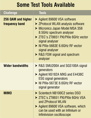
The advanced methods utilised in WLAN 802.11ac present new challenges to design engineers working with this standard. Next, we discuss these challenges and solutions available that help in designing new products based on this standard.
256 QAM and higher frequency band
Quadrature amplitude modulation (QAM) scheme is used to convey a message signal inside two carrier signals so that they can be physically transmitted with better throughput. The two carriers are out of phase with each other by 90°, which makes them quadrature signals. 256 QAM is used because a higher-order QAM makes it possible to transmit more bits per symbol.
 The higher-order 256 QAM requires lower error-vector magnitude (EVM) or constellation error in both the transmitter and the receiver as the constellation points are closer together. EVM problems may be caused by carrier leakage, phase noise in the local oscillator or amplifier non-linearity. Vector signal analyser (VSA) is a valuable tool to measure and identify the causes of poor EVM.
J.K. Baldua, director-technical, Scientech Technologies, says, “A high-resolution spectrum analyser of at least 6GHz range preferably with a tracking generator for monitoring channels, channel width, channel power, etc is required.” Since 802.11ac standard utilises the 6GHz band, spectrum analysers need to be able to handle this as well as the higher bandwidth that 802.11ac requires.
Wider bandwidths
802.11ac features a wider bandwidth of 80 or even 160 MHz against the previous maximum of 40 MHz featured in the 802.11n standard. A wider bandwidth results in an improved maximum throughput for the digital communication system.
Amongst more complex challenges for design and development is the generation and analysis of wider-bandwidth signals for 802.11ac. Testing equipment able to handle 80 MHz or 160 MHz will be required to test transmitters, receivers and components.
For generating 80MHz signals, many RF signal generators do not have a high enough sampling rate to support the typical minimum 2x oversampling ratio, which can result in unnecessary images (i.e. upper sideband and lower sideband) in the signal, due to aliasing. Using proper filtering and oversampling of the waveform file, it is possible to generate 80MHz signals with good spectral characteristics and EVM.
To generate 160MHz signals, a wide-band arbitrary waveform generator (AWG), such as the Agilent 81180A, 8190A or M9330A, can be used to create the analogue I/Q signals. These signals can then be applied to the external I/Q inputs in a vector signal generator for up-conversion to RF frequencies. It is also possible to create a 160MHz signal by using 80+80MHz mode supported by the standard to create two 80MHz segments in separate MXG or ESG signal generators and then combining the RF signals.
MIMO
MIMO is the use of multiple antennae to improve the performance of the communications system. You might have seen certain Wi-Fi routers having more than one antenna sticking out of them. These routers use MIMO technology.
Verifying MIMO design is a challenge. Multi-channel signal generation and analysis can be used to provide insight into the performance of MIMO devices and assist in troubleshooting and design verification.
For testing receivers, MIMO signals can be created with both the SystemVue WLAN library and Signal Studio. Multiple MXG or ESG signal generators can be synchronised to simulate the output of a MIMO transmitter. The effects of the fading channel can also be included in the waveform files to provide simulation of the signals at the receiving antennae.
For MIMO transmitter test, the 89600 VSA software can be used with an Infiniium or Infiniivision oscilloscope to provide analysis of up to four channels. The analysis includes EVM and IQ measurements for all channels as well as cross-channel metrics such as the frequency response of each channel and the channel matrix. ZTEC’s ZT8651 PXI/PXIe 6GHz VSA and ZProtocol WLAN offer testing covering all aspects of the 802.11ac protocol including X2, X3 and X4 MIMO streams.
Baldua says, “A digital storage oscilloscope (DSO) having 200MHz bandwidth and 1Gsps sampling is required to observe real-time signals.” An example of such a DSO is the Scientech NB100C2 series.
Amplifier linearity
Amplifier linearity is the characteristic of an amplifier by which the output signal of the amplifier remains faithful to the input signal as the signal drive increases. Real amplifiers are linear only to a limit, after which the output saturates.
There are many techniques to improve amplifier linearity. Digital pre-distortion (DPD) is one such technique. Design automation software like SystemVue provide an application that simplifies and automates digital pre-distortion design for power amplifiers.
Sadaf Arif Siddiqui, technical marketing specialist from Agilent Technologies India, explains, “The SystemVue Builder software generates a stimulus waveform which is downloaded to a radio frequency (RF) signal generator and then applied to the power amplifier. The system captures the amplifier’s response using a signal analyser and compares the result with the desired signal to create the pre-distortion matrix. The pre-distorted signal is then sent to the power amplifier and the response checked.”
