


The first part of this article covered defensive combat operations, air defence warfare, fighter aircraft and AEW aircraft combo (phase I), and air search radars and fighter aircraft combo (phase II). Read on:
Phase III: Operations: Aegis accompaniments
Destroyers and cruisers associated with the carrier are called Aegis ships, which are equipped with a robust command and control (C2) system called Aegis. These ships are more potent due to the presence of superior radars and C2 systems, which are based on high-performance computers.
Aegis cruisers are well-suited to conduct air defence warfare due to their superior array of radars. These have 2D long-range air-search radar AN/SPN-49, which is also present in the carrier. This radar is followed by passive electronic phased array radar AN/SPY-1.
Aegis destroyers do not have AN/SPN-49 radar. Hence, these cannot detect threats from a long range. Aegis cruisers with AN/SPN-49 radars detect threats at a long range and then Aegis C2 system lets the threats of interest to be tracked by AN/SPY-1 radar.
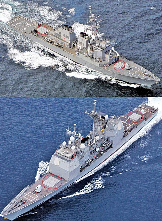
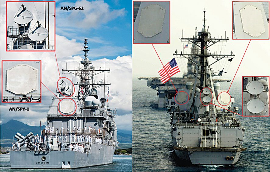
AN/SPY-1 multi-functional radars. These are phased-array radars, which are the latest-generation radars that were introduced in the 1980s and are still state-of-the-art. These have antennae composed of many transmitting and receiving (T/R) elements. Each element radiates and receives RF energy individually, a sort of many tiny antennae arranged into one big antenna. A single source supplies RF energy to all T/R elements through computer-controlled phase shifters.
The radar computer controls the direction of the beam by varying the phase of the RF signal emitted by each T/R element. In time-domain analysis, the signal to each T/R element is delayed for a certain duration by these phase shifters. By suitably varying the phase (suitably delaying), a wavefront of electromagnetic energy is formed in the desired direction. In simple words, a beam is formed. A moving beam is formed by varying the phase accordingly. This technique is called electronically slewing the beam, in contrast to mechanical slewing.
In mechanically-slewed radars, position of the beam is constant with respect to the antenna. So the antenna itself must be slewed for scanning targets. The ability to slew rapidly is called agility. For rapid scanning requirements, the antenna must be slewed rapidly. But there are mechanical limitations beyond which the antenna cannot be slewed.
In AN/SPY-1 phased-array radar, the beam-formation technique provides agility for rapid slewing. Since the phase is varied by a computer, the direction of the beam can be switched in microseconds; there is no need for the antenna to move at all. Because of this, the antenna of this radar is not fixed in any mast but embedded on the superstructure of the vessel itself.
Using this technique, many individual beams can be formed depending upon the requirement for various functions, with each beam performing a specific function like scanning, tracking or providing datalinks. A single radar antenna covers a 90° sector in the azimuth and from the horizon in the front to the zenith overhead in elevation.
There are four antennae for this radar to cover a total of 360°. In this arrangement, a hemisphere of RF energy is maintained around the ship up to a range of around 185km (100-nautical-miles). The radar’s peak power is 4MW to 6MW and average power of 58kW in the S band.
Next in the line are the missiles for engaging the target.
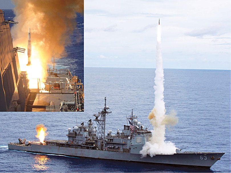
SM-2 SAMs. The surface-to-air missile (SAM) used in Aegis vessels is called Standard Missile-2 (SM-2). Its range is quite long and current versions are capable of engaging targets even up to 200km. The guidance scheme of SM-2 is a semi-active radar-guidance scheme.
Generally, due to the long range involved, majority of long-range SAMs have semi-active radar-guidance schemes. This means that these do not have radar transmitters but only radar receivers. These can only receive radar echoes but not chirp out radar signals like usual radars. These depend on other radars for guiding these to intercept the target.
Due to the longer engagement range, more radar signal strength is required to look for the target. For more signal strength, the missile must have ultra-strong batteries to pump enough amperes into the radar. But ultra-strong batteries are heavy and consume more space in the missile. This extra weight introduces restrictions in the missile’s manoeuvrability.
Due to these reasons, the missile only has the radar receiver section as the target seeker. As reception does not involve huge power requirements, the receiver fits snugly into the requirement. The ship, which launches the missile, provides radar energy through an illumination-/fire-control radar. This radar does not chirp out pulses but continuously focuses its high-energy radar signals on the incoming target. Reflected energy is picked up by the missile seeker.
The missile’s guidance system understands the position of the target due to the directional property of this received radar energy. Then, the guidance system aligns the missile for successful interception and intercepts the target to destroy it.
In Aegis cruisers and destroyers, SM-2 missiles are stored in a vertical launching system (VLS), which can hold 122 missiles in total and those present in destroyers can hold 96 missiles.
VLS is a generalised launcher system and can launch many types of missiles. Though depending on mission requirement, various types of missiles could be loaded to this VLS. For complex missions, entire VLS could be loaded with SM-2 missiles.
AN/SPG-62 illumination-/fire-control radars. This radar operates in I/J NATO frequency band (8GHz-20GHz) with a peak power of approximately 10kW. It is a continuous-wave illumination radar and does not chirp out signals as pulses. Instead, it focuses its energy as a fine pencil beam on the target, like focusing a flashlight on an object. Due to this, this radar is called an illumination radar.
In military parlance, this is known as painting the target. This radar is mechanically turned to steer the beam. There are four such radars in Aegis cruiser; two are rearward-facing and two are forward-facing. This arrangement provides 360° coverage. With each radar illuminating a target, these radars can illuminate up to four targets.
Aegis destroyers have three of these radars and the absence of AN/SPN-49 radar leaves it with lower air defence capability. This makes Aegis cruisers a prime node in the air defence architecture of CSG defending against cruise missile strikes.
Typical engagement sequence
In the engagement sequence, first, incoming target is detected through AN/SPN-49 surveillance radar. Aegis C2 system directs that target to be tracked by AN/SPY-1 radar. From this tracking, the target’s trajectory is derived in Aegis C2 system and the target’s future course is computed. Then, the point of interception is calculated, which is a place where the target can reach in a few moments. SM-2 SAM is launched to reach this interception point through midcourse guidance.
Due to the very long range involved, the parent vessel gives commands for the missile to fly, which is called midcourse guidance. These commands are supplied through a datalink, typically a radio channel. The missile receives this information through the datalink and flies accordingly. AN/SPY-1 radar provides this datalink too.
By the time SM-2 approaches incoming target, Aegis C2 system directs the fire-control radar to illuminate the incoming target. When the missile reaches an optimum distance from the target, it starts using its radar receiver and guides itself towards the target.
AN/SPY-1 allows many such beams to be formed. Because of this, many datalink channels can be established so that many SM-2 missiles can be given guidance commands. This enables many missiles to stay on air to intercept the same target or multiple targets.
Similarly, Aegis C2 system time shares illumination radars for a large number of targets to neutralise simultaneous cruise-missile strikes. The number of targets that could be engaged through this feature is kept as classified information. But without this time-sharing feature, the number of targets intercepted will be equal to the number of fire-control radars.
Cooperative engagement capability, the latest trend
As the CSG’s cruise missile defences increased in capability, the Soviets fielded faster cruise missiles; some of these cruise missiles were even capable of covering a kilometre in a second. Because of this high speed, reaction time for the CSG decreased to a great extent. Windows of interceptions also reduced for the CSG against these faster cruise missiles.
The Soviets also increased the range of cruise missiles. They augmented the number of cruise missiles carried by cruise-missile-carrying platforms. Soviet submarines, surface vessels and bombers were able to carry more cruise missiles in a compact manner. So, more number of cruise missiles of lethal speed could be fired from longer range and also in greater numbers.
Though Soviet Union is defunct now, Russian Federation and China have this cruise missile strike capability. To defend from this renewed attack of fury, American CSGs needed a new deal in cruise missile defence.
Cooperative engagement capability (CEC) is the new sinister air defence scheme of USN. Ironically, CEC has not been achieved through addition of any new radars or weapon systems but by sharing these. Through this sharing, the capability level of air defence has increased exponentially. This is the first step towards a futuristic warfare called network centric warfare (NCW).
In CEC, tracking data from radars present in the destroyers and cruisers is shared using identical algorithms. Each ship tracks a target with a radar and, simultaneously, sends this data to other ships. Each individual ship receives data and fuses it with its own radar data. This is carried out by employing high-capacity parallel-processing computers and advanced fusing algorithms. The result is that, all individual ships see a common air defence scenario called air picture.
Earlier a destroyer or a cruiser could view the threat scenario on the air around it. But through CEC, the same vessel can now see the threat scenario on air around the entire CSG.
The backbone of CEC is a robust communications system, which is jam-resistant and utilises the advantages of GPS. Ships communicate in pairs in 500MHz to 1000MHz band during short transmit/receive periods to a line-of-sight (radar) distance. Data thus sent across the net is in near real-time, and communication is virtually jam-proof because of superior jam-resistant features.
The single greatest advantage is that a ship may not be seeing an incoming cruise missile through its radar, but can launch and guide a SAM to intercept the incoming cruise missile based on fused track data sent by other ships. Similarly, a ship may launch a SAM with another ship providing midcourse guidance with yet another ship illuminating the target.
For example, a single ship’s radar may be able to detect a cruise missile at 40km from the ship. If the cruise missile is travelling at a speed of 1mach (330m/s), then it will reach the ship in 120 seconds. So the ship has to intercept the incoming missile within two minutes to prevent sinking.
Assume that there are two CEC equipped ships, A and B, operating 40km apart on a straight line. Ship A detects a cruise missile at 40km from it along its axis and the cruise missile is flying towards ship B. Through CEC, as ship A detects the cruise missile, ship B also detects it. Now, the cruise missile has been detected at 80km from ship B against its 40km-detection capability. Due to this, ship B now sufficiently has four minutes to intercept the missile. This feature greatly relieves the pressure on ship B, when it is operating near the shores.
With CEC, each individual ship is made to scan a specific sector and data from all ships is fused into a single air picture. Interestingly, two CSGs operating in close proximity can share the data. This enables both to have an overall air picture common for both strike groups.
Such capabilities have been achieved for the first time in history and even been deployed operationally.
Phase IV: Terminal air defence
This phase is almost a cruise missile defence phase executed by the carrier, but can also tackle enemy aircraft, if at all enemy aircraft survive the previous air defence phases, which is a near impossible feat. But with cruise missiles, it is a different story.
Cruise missiles fly so low as if these are skimming over water surface. This flight profile helps these to hide among clutter, that is, echoes from the sea surface. With this flight profile, these may still escape interceptions carried out by Aegis vessels and reach the carrier, generally considered remotely possible. An enemy aircraft or cruise missile reaching this phase means that Aegis vessels have been neutralised.
For the carrier, there are two defensive lines against cruise missiles. One is through Sea Sparrow SAM system and the other is through ship self defence system (SSDS). AN/APS-49 and AN/APS-48 radars of the carrier provide coordinates of the targets in the initial phase of engagement.
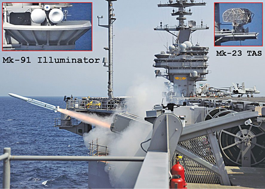
Evolved Sea Sparrow SAM system. Evolved Sea Sparrow is the name given to SAM. The entire system consists of a target acquisition radar called Mark-23 target acquisition system (TAS), an illuminator radar and missile launchers, all tied up to a fire control system (FCS) called Mark-91.
FCS is the point of man-machine interface. It is this FCS which has the FIRE switch to launch the missile. Missile launchers are situated at two places in the carrier; one is on the left side front of the carrier and the other is on the right or left side aft of the carrier. Each launcher carries eight missiles in ready-to-fire mode. SAM, on the side of the incoming cruise missile, is fired to intercept the threat. Also, the carrier is manoeuvred so that more SAM launchers face the side from where maximum number of cruise missiles are incoming. This creates a crossfire area where two SAM systems can target the threats.
Evolved Sea Sparrow missile. The evolved Sea Sparrow SAM has a semi-active radar-guidance system with midcourse datalink update scheme, like SM-2 SAM. It has an interception range of more than 50km.
Through AN/SPN-48 radar, high-flying targets are identified and tracked. The engagement passes on to Mark-23 TAS. For low-flying cruise missiles, Mark-23 TAS directly comes into play.
Mark-23 TAS. Mark-23 is a 2D pulse-Doppler acquisition radar. It operates in 1GHz–2GHz (L band) and has been specifically designed to operate in high-clutter environments. The radar can detect a target with a radar cross-section (RCS) as minimum as 1m at ranges around 40km. Generally, cruise missiles have low RCS. The radar automatically starts tracking the fast-approaching cruise missiles.
This radar can also be used for aircraft traffic control in a secondary role. In this role, the range is around 185km.
This radar is gyro-stabilised and can tackle 30° pitches and rolls. It provides 360° coverage and up to 75° coverage in elevation. It rotates at 15rpm during normal azimuthal scanning. But under threat scenarios, it can rotate at 30rpm to track the target intensely. It can simultaneously track 54 targets. The desired target to be intercepted is chosen in the FCS. Then, illumination radars come into play being initiated by the FCS.
Mark-95 illuminator. This radar operates in X band and produces 2kW average power. Generally, X band radiators are capable of producing a thin beam, which is essential for accuracy and resolution. This radar houses transmitter and receiver antennae separately. Cylindrical structures are radomes. Concave and convex radomes enclose receiver and transmitter antennae respectively. Between these two is an electrooptical imager for electrooptical tracking, as a backup arrangement. There are four Mk-91 illuminators in a carrier.
In a saturation cruise missile strike against the carrier, there are many cruise missiles flying towards the carrier. There is a serious possibility that one or two cruise missiles escape interception from Sea Sparrow air defence envelope. The last resort is the ship’s self-defence system (SSDS).
The SSDS
SSDS is the second line of the carrier’s air defence. For a carrier there is a possibility of at least one incoming cruise missile in all eight directions during a saturation cruise missile strike. In this scenario, even a second lost in decision making implies destruction. So what claims importance here is prioritising threats and engaging these sequentially and, most importantly, quickly. For this, a decision-making automatic C2 system is required. SSDS is a system to neutralise these low-flying cruise missiles.
This is not a new system; it is simply a fibre-optic local area network (LAN) around an SSDS C2 system, connected with self-defence weapon systems like rolling airframe missile (RAM) and close-in weapon system (CIWS) called Phalanx, and sensors like long-range air-search radar AN/SPS-49, surface-search radar AN/SPS-67 and a centralised IFF system, and an electronic warfare suite.
The irony of SSDS is that, this integration in no way augments the individual system’s efficiency from its standalone capability. But integration reduces the reaction time during complicated cruise-missile-attack profiles. Data from all sensors are clubbed to form a single tactical picture in the computer. Tracks are analysed, threats are identified from the tracks. From here, threats are prioritised and finally engaged through a suitable weapon system.
For example, if two cruise missiles are approaching the carrier from different directions, the one closer to the carrier is given priority and engaged.
Though this system is an automated C2 system, it has a manual override feature. For the commander, SSDS suggests the mode of engagement for incoming targets. In manual mode, it leaves the responsibility of engagement to the operator. In automated mode, it takes care of the engagement itself. This automation reduces the time taken from detection to engagement.
AN/SPS-49 long-range air-search radar. This radar can detect incoming cruise missiles and aircraft flying very high but has restrictions in detecting low flyers.
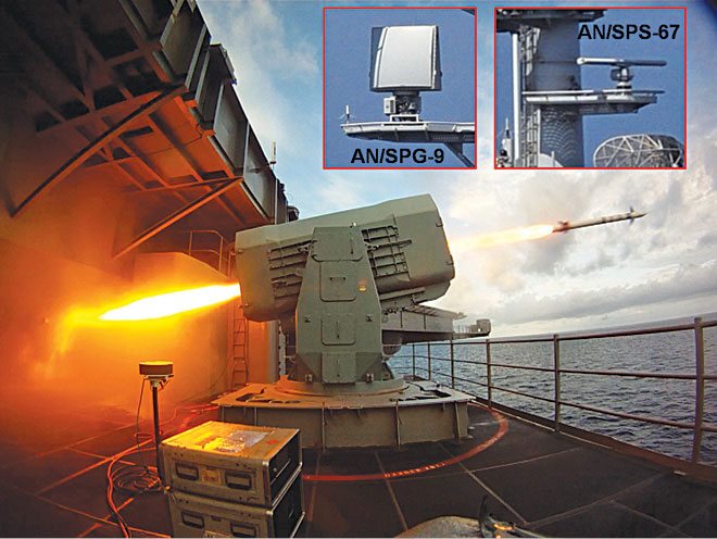
AN/SPS-67 surface-search/navigation radar. This is a 2D radar that operates in 5450MHz to 5825 MHz region (G band). It is used for surface surveillance and navigation. This capability of the radar results in it having a secondary capability of detecting low-flying cruise missiles. The radar’s detection range is around 100km and it is capable of a peak power of 280kW.
It is flexible in a way that pulse widths and pulse-repetition frequencies (PRF) of radar energy can be varied, accordingly, for the desired resolution. A higher PRF setting and short pulse width increases the resolution to detect two smaller targets in close proximity to each other. Other settings may even show these two targets as a single large target. But other settings also have different uses; the operator chooses the settings accordingly.
AN/SPQ-9 air and surface surveillance radar. This is an air and surface surveillance X band-phased array radar. It covers 360° in azimuth at the rate of 30rpm. This allows the radar to detect sea-skimming missiles at the horizon against the presence of heavy sea clutter. It automatically displays any target with a relative speed exceeding ten knots. It complements high-altitude surveillance radars by detecting missiles that are approaching just above sea surface.
In surface mode, it generates a separate surface frequency to detect surface targets. It can even detect a submarine that has partially submerged and is just peeking its periscope above the water surface.
The radar is present in Aegis vessels also, where it helps these to fire accurately on the enemy surface vessels.
Rolling airframe missile (RAM). This missile is carried in bulk in its launcher. It is capable of reaching mach 2 speeds with an effective range of 9km. It is independent of any radar and has a passive radar-homing guidance. It targets the incoming cruise missile by homing on its radar emissions.
Generally, anti-ship cruise missiles have radars as seekers. RAM looks for radar emissions, finds these, locks on these and flies towards these. Also, RAM can target infrared (IR) emissions that are abundantly available in the incoming cruise missile’s engine exhaust. As the missile’s exhaust is very hot, it emits IR radiations like a hot iron emitting red light.
Both Sea Sparrow and RAM have a minimum range beyond only which these can engage. These need time, at least a fraction of a second, to pick up maximum speed. The range at which these pick up maximum speed is their minimum range. It is highly difficult for RAM to manoeuvre towards the target before the minimum range with speed building up. If the incoming cruise missile escapes interception and closes in rapidly, air defence warfare progresses to close in defence.
Phalanx close-in weapon system (CIWS). CIWS is a rapid-firing Gatling gun. Gatling guns have rotating multiple barrels. Gatling gun, developed by Richard Gatling, was the first machine gun in the world. In the past, the gunner had to rotate a crank handle to rotate the barrels in the first Gatling machine guns. But CIWS uses motors for this purpose. At an astounding rate, CIWS shoots tungsten or depleted uranium tipped bullets. These bullets are known for their hardness, so the sheer number of these fired can literally shred incoming cruise missiles into pieces.
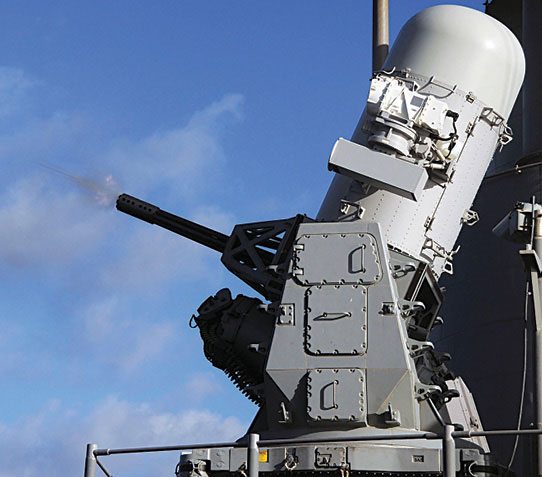
How does this last line of CIWS defence work? CIWS is generally kept as an independent and automatic system but with manual override features. It has its own set of radars, a search radar and a tracking-cum-fire-control radar, to ensure last-resort air defence capability. For example, if SSDS connectivity is lost, CIWS can take care of missile defence.
These radars operate at 9200MHz-9250MHz band and are capable of emitting energy at a peak power of 1.4kW. The search radar keeps on scanning its sector around the carrier. If a target appears, it gives the bearing, range and altitude of the target to the FCS of CIWS.
FCS first checks if the target is approaching the carrier. If it is outbound, CIWS discards it. But if it is inbound, the track is taken as bogey (possible enemy). Now, FCS determines whether the bogey is in a collision course with the carrier by extrapolating the trajectory of the bogey through radar data. It also checks the speed of a bogey that presently is not in collision course. It does this to determine whether the target can manoeuvre to a collision course at a later stage.
If these assessments are positive, FCS instructs the tracking radar to start tracking the bogey. When the bogey reaches within the gun’s range, FCS commands the gun to start firing. Guns fire at a point where the bogey arrives in a few fractions of seconds. The tracking radar also tracks the trajectory of the bullets to check if these deviate due to any environmental parameters. If so, FCS fires the guns accordingly to offset the deviation.
Typically, CIWS first finds the targets at 8km from the carrier. If it detects that the target is inbound and flying between speeds of 140 knots and 1600 knots, it starts tracking the target at 5km. CIWS can detect and track a target flying at an altitude of 8km.
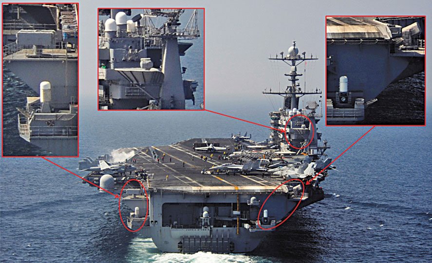
A typical USN carrier has three CIWS located strategically at the corners. So at any point of time, two CIWS can engage a single bogey to maximise the chance of destroying it. Each Aegis destroyer and cruiser has two CIWS to protect themselves.
Latest CIWS versions have EO sights (thermal imaging cameras) for the operator to distinguish a bogey from a friendly aircraft with his own eyes even in dark. Since CIWS does not have an inbuilt IFF, only SSDS supplies IFF data. So if SSDS connectivity is degraded, in automatic mode CIWS considers even a carrier-borne aircraft approaching to land as bogey and shoots it down.
Electronic warfare (EW) suite. The EW suite is also integrated with SSDS to divert the missile by spoofing it. This spoofing attempt is the soft killing of the incoming missile. It may precede a SAM interception or take place along with the interception.
B. Kamalanath is a technical writer. He is also a research scholar, pursuing Ph.D in military technology