Modern electronic warfare (EW) system developers are facing multiple challenges including increased spectral congestion and surveillance of wider bandwidths at a greater level of detection sensitivity. In addition, the push on system developers to reduce development times strains many of the existing development models, resulting in custom hardware and firmware designs to achieve improved levels of performance within size, weight, and power constraints. New giga sample per second (GSPS) high speed converters, high performance field programmable gate arrays (FPGAs), and FPGA intellectual property (IP) cores are now changing the status quo, providing designers with off-the-shelf solutions and configurable building blocks to meet the next generation of challenges. A reference design, featuring GSPS analogue-to-digital converters (ADCs) with FPGAs and channelisation IP, will show how designers can achieve faster time to market with state-of-the-art solutions for electronic intelligence and digital RF memory systems.
EW Overview
EW systems identify and counter electronic threats such as surveillance and tracking radars. EW systems are commonly categorised as either electronic support (ES), electronic attack (EA), or electronic protect (EP). ES systems intercept and measure signal parameters to identify the signal’s sources and perform threat analysis. The EA systems generate jamming signals to overpower the true pulse. Digital radio frequency memory (DRFM) is a spoofing technique to deceive radars. The EP systems concentrate on processing and storing the incoming signals to construct a signal database. This database is a continuously updated lookup table used to identify future radar systems. Traditionally, these systems were developed on an analogue platform. Modern systems are significantly more digital to take advantage of the signal processing capabilities available in the programmable logic devices. Threat detection from unknown targets in these systems requires a receiver, which can operate over a wide frequency band to identify and initiate countermeasures to the threats. Typical EW systems may operate over a range from DC to 20GHz. Beyond wide bandwidth requirements, practical EW systems require high dynamic range, high sensitivity, and accurate pulse characterisation as new systems are being pushed to examine the bandwidths of interest faster with greater levels of detection sensitivity. More complicated situations arise when incoming signals to the EW system may be from numerous sources, each of which needs to be identified and distinguished. Independent of intentional interference from adversaries, increased spectral congestion, particularly from the rapid expansion of communications infrastructure, has made effective detection even more challenging. Complex systems with even lower size, weight, and power targets are driving longer development cycles. However, next-generation, off-the-shelf solutions coupled with programmable building blocks provide solutions to these challenges. Two of the key building blocks critical for any EW system, the analogue-to-digital converter and real-time channelisation IP, will be examined further to illustrate how these challenges are being addressed.
ADC Bottleneck in EW Systems
In many instances, the high speed ADC transition from the analogue to the digital domain is the limiting factor in ES, EA, and EP systems, where the system architect is often faced with a conundrum. While minimising cost and system size are usually the top priority, the system designer must also strike an optimal balance between the need to increase instantaneous surveillance bandwidth to maximise the probability of interception, and how to minimise the effects of in-band, high power signals that desensitise the system. These requirements pose challenges in the converter design and the front-end design that couples the signal content to the converter. Even if the converter itself has excellent performance, the front end must be capable of preserving the signal quality, which results in the relentless push for performance and cost on the limits of high speed ADCs. Figure 1 illustrates a simple EW system. The key features of the system are an RF receiver, used to down-convert and select the band of interest for interrogation, the ADCs used to transition the data from the analogue-to-digital domain and the digital signal processing engine, which is typically an FPGA configured to detect, determine, analyse, and manage the storage of signals of interest. DRFM and EA systems also include a corresponding transmit chain utilising a high speed digital-to-analogue converter (DAC).
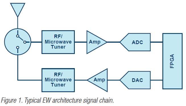
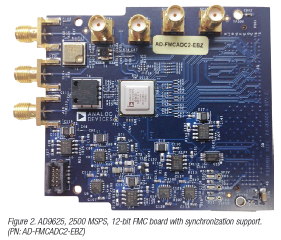
Historically, increasing the instantaneous bandwidth while maintaining the required linearity required using either multiple overlapping receivers or an interleaved architecture. The overlapped receivers each digitise a portion of the required bandwidth with digital signal processing used to recombine the data and observable spectrum from each channel. For interleaved architecture, it is often used with calibration required to minimise the phases, offset, and gain differences between the converters. Both options are generally expensive to implement but the digital signal processing is often customised to the implementation. RF sampling ADCs such as the AD9625 offer solutions to the next generation of systems providing greater instantaneous bandwidth but with higher linearity to maintain the sensitivity levels required. Such ADCs also support synchronising of multiple converters, often required for angle of arrival determination, and has integrated digital down-converters (DDC) to decimate and observe a smaller portion of the frequency spectrum on the output. Devices that support parallel and serial interfaces (including the JESD204B standard) are important to support the high data rate and low latency requirements in many of the EW systems.
Channeliser Overview
Despite particular signal characteristics in EA, ES, and EP systems, a common component is the digital channelised receiver, or channeliser. The channeliser splits a wide bandwidth into smaller ones to separate signals of interests from noise and interferers so that low signal-to-noise ratio (SNR) and time sensitive signals can be reliably detected in individual subchannels. Most digital channelised receivers consist of a filter bank and fast Fourier transform (FFT).
As a design engineer, one of the challenges here is that every new EW design or upgrade usually requires developing a more complex channeliser. This is because new designs usually bring about necessary upgrades in hardware, providing for higher speed converters and more processing performance essential to keep up with ever changing global threats. To accelerate the development of the channeliser and reduce internal research and development (IRAD)cost, we use a super sample rate FFT IP and FIR filter IP core capable of handling multi-GSPS converter inputs. These IP cores will optimise a solution for you based on a wide set of input parameters, as shown in Figure 3.
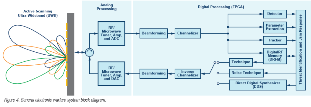
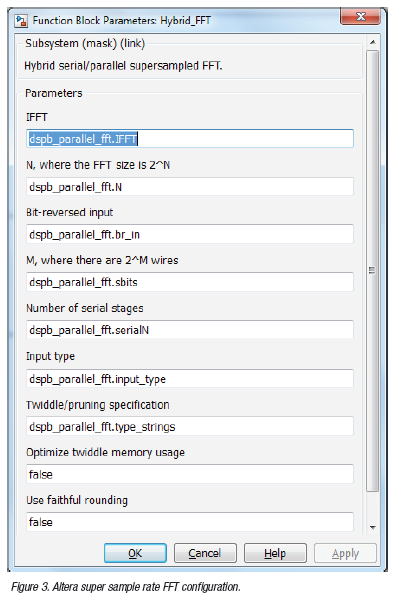 Figure 4 depicts the role of the channeliser in a general EW system block diagram, in which the digitised incoming radio frequency (RF) wideband signal is down-converted, and digitised before feeding into the channelised receiver. Signal detection and estimation are performed on individual channel outputs to discern threats from neutral and friendly signals. Once threats are identified and data based, cfertain EW systems will counter the threats through jamming. In this process, the receiver may produce various jamming signals. These jamming signals can appear in the forms of notched white noise or regenerated false reflection signals, that is, DRFM, to the hostile transmitter. The jamming signal passes through the inverse channeliser, whose role is to reconstruct a wideband reflection signal. The reflection signal is emitted after up-conversion back to the hostile transmitter.
Hardware Demonstration
The project demonstrates the ADC interface and the channeliser function. A signal generator produces a sinusoidal tone as the ADC input. The ADC output is connected to the system-on-chip (SoC) development kit using the industry-standard FPGA mezzanine card (FMC) interface. The JESD204B standard defines data rates to logic devices in various lane configurations. The JESD204B interface in this demonstration is configured to use the 8-lane transceiver mode, as shown in Figure 5A and Figure 5B. The samples received over JESD204B interface are fed into the channeliser IP, which is configured to receive 16 samples concurrently using 16 input wires (Parameter M in Figure 4). Depending on the number of fast Fouriet transform (FFT) points, a full FFT frame is divided into multiple time slots. For example, a 1024-point FFT requires 1024/16 = 64 time slots to complete. Filter bank coefficients and FFT processing stages switch automatically according to the time slot. Channeliser IP was developed using tools like DSP builder advanced (DSPBA), a model-based design flow tool from Altera that enables design, evaluation, and verification of algorithms in MATLAB/Simulink environment. Once the algorithm is optimal, DSPBA generates a code that can be deployed on FPGAs.
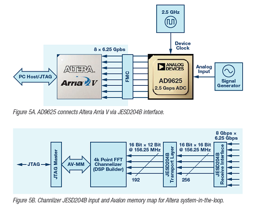
The channeliser output is stored in on-chip memory and is verified through system-in-the-loop (SIL) tool, which uses a MATLAB API to trigger on-chip registers to start logging for data visualisation. Once triggered, a single iteration of FFT processing is executed and the resultant data is stored into on-chip static random-access memory (SRAM). The MATLAB API extracts data through the memory map from SRAM to a MATLAB host. Once uploaded to MATLAB, the samples are plotted on the screen.
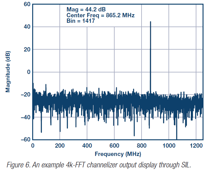
The channeliser can switch to different FFT size easily through a MATLAB setup script. Such flexibility ensures a future upgrade path and potential design reuse across different system configurations. As an example, Figure 6 shows a 4096-point FFT output from the SIL.
Faster EW solutions
Next-generation high speed converters offer solutions to provide higher instantaneous bandwidth without compromises on system sensitivity, and provide more flexibility in frequency planning or relieve a mix downstage on the front-end RF strip. However, achieving bandwidth data analysis in the 1GHz range can pose challenges to designing a high performance system.
To solve this problem, channelisers can be used to analyse these wide bandwidths while maintaining high performance. The GSPS RF ADCs coupled with configurable channeliser IP cores provide next-generation system designers a faster solution to the ever changing electronic warfare environment.
Rob Reeder is a senior system applications engineer in the Aerospace and Defence Applications Group, and Duncan Bosworth is the director of marketing and applications in the Aerospace and Defence Business Unit at Analog Devices Inc. Ronak Shah is the system engineer and manager, and Dan Pritsker is a senior system design engineer at Altera Corporation.


