
Watchdog timer based system design
The software needs to kick the watchdog constantly. In some implementations, a sequence of bytes is needed to be written in the watchdog register to kick the watchdog. This reduces the chance of an errant code that might accidentally kick the watchdog.
After WDT overflows, it will assert the processor reset line. Some processors and controllers can generate an interrupt before resetting the device, which is like an early warning for an upcoming watchdog reset. We can save useful information like status register in a non-volatile memory by reading this information after recovery. From reset logs, we can debug the root cause of the reset.

A watchdog can also be used to wake up the device from sleep or idle mode. In sleep mode, watchdog timeout will not reset the system, but just cause it to wake up.
Simply enabling WDT and kicking it regularly is not enough to ensure system reliability. To get optimum benefit, implementation of the watchdog is a must for robust design.
Watchdog time-out period
For selecting watchdog time-out period, we must have a proper understanding of the software loop latency. An unusual number of interrupts may happen during a single scanning of a loop, and the extra time spent in the interrupt service routine (ISR) will increase the main loop latency. A software delay routine will also increase loop latency. The design with delays in various places in the code has control of the watchdog, which can prove to be problematic.

For some time, critical application and recovery time from the watchdog reset is very important. In such a system, time-out period needs to be very precise. After watchdog reset, the system must boot-up as fast as possible. For example, in case of a pacemaker machine, the system must boot-up almost within a heartbeat. The initialisation after a watchdog reset should be much shorter than power-on initialisation.
Very short time-out periods may lead to the system resetting unnecessarily. If the system is not time-critical, it is better to choose time-out in seconds.
Implementation of watchdog timer for single-thread software design
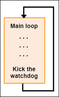
The traditional approach for a single-thread design is to kick WDT at the end of the main loop.
In a single-thread design, we can use state-machine-like architecture as shown in the code snippet below. Increment the state variable value at three different sections of the code, which will definitely iterate once in a one-loop scan. At the end of the main loop, check the state value; if it is three, it means that the code execution is done in proper sequence. Then, kick the watchdog and clear the state flag. If the state value is not three, it means there is some fault in the execution of the code. In this case, do not kick the watchdog, else the system will reset after watchdog time-out.
—————-CODE——————
main ()
{
for( ; ; )
{
if(State == 0) State = 0x01;
. . .
. . .
if(State == 1)State = 0x02;
. . .
. . .
if(State == 2)State = 0x03;
. . .
. . .
If (State == 0x03)
{
Kick the watchdog
State = 0;
}
}
}
—————-CODE——————
On some microcontrollers, the built-in watchdog has a maximum time-out of the order of a few hundred milliseconds. But, if the main loop scan time is higher than the maximum allowed watchdog time-out, we need to multiply that in the software.
For example, main loop latency of 500ms and maximum allowed watchdog time-out period of 100ms (which means that the watchdog must kick before 100ms) is not possible from the main loop. In this case, we can configure the processor’s internal timer to 50ms free-running and define flag state at the end of the main loop set and state it as Alive.
—————-CODE——————
main ( )
{
for ( ; ; )
{
. . .
. . .
State = ALIVE;
}
}
—————-CODE——————
In every 50ms ISR increment count, check state flag. Only kick the watchdog if state is not Unknown. When the count reaches above ten (500ms time is elapsed), ISR again and check state flag. If state is Alive, it means that the program is running correctly. Otherwise, set state as Unknown. This represents that there is some problem in the execution of the code and so ISR will not kick the watchdog anymore and the system will restart after watchdog time-out of 100ms.
—————-CODE——————
ISR() //50ms free running
{
Count++;
If(Count > 10) //10x50ms
{
Count = 0;
If(State == ALIVE)
{
State = RESET;
}
else
{
State = UNKNOWN;
}
}
If (State != UNKNOWN)
{
Kick the watchdog
}
}
—————-CODE——————
Never kick the watchdog in an ISR unconditionally or devote an RTOS task to this activity, because, if the main code crashes, interrupts (and even the scheduler), it may continue to run so the watchdog never times-out. However, this approach is not recommended as we have no idea if the code is working, or not, except the timer ISR.
Implementation of watchdog timer for RTOS based application
In a multitasking environment, there are a couple of independent loops running in parallel, known as tasks. The scheduler schedules each task based on priority. To validate that each task is running properly, each task must contribute in the decision of kicking the watchdog.
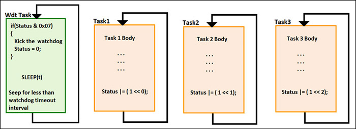
To implement the watchdog mechanism in an RTOS environment, we can design a separate task that will monitor the status of all running tasks—we can call this the watchdog task. Only this task gets the privilege of kicking the watchdog.
Let us take an approach in which there is a status byte and each bit of this byte is associated with a task. For example, our system has three tasks running and each task will set corresponding bits in the status flag at the end of its body.
When the watchdog task wakes up, it will check whether all three bits are set (which means whether all tasks are running properly). It will kick the watchdog and clear the status flag. In this case, the priority of the watchdog task must be lower than other system tasks. Once the watchdog timer execution is completed, it goes in sleep mode for less than the watchdog time-out period.
The approach for the watchdog design for an RTOS (Fig. 4) will work well if all tasks are executed once in less time than the watchdog reset period, including watchdog task. But if any of the tasks go in sleep mode for a couple of seconds, or have to wait for an event, the above approach will not work in this design.
We can implement it in a better way by using the message queue, where each task blocks at the message queue. The watchdog task will post messages to all tasks and go in sleep mode for a specified time interval (less than the watchdog time-out period).

After the arrival of the message in the message queue, the task will wake up one by one based on priority. Each task reads the message and if the task has been woken up by the watchdog task, it will set the corresponding bit in the status flag.
When the watchdog task wakes up, check the status flag. If it has all corresponding bits set, kick the watchdog and clear the status flag. In this approach, the watchdog task must have higher priority than all other system tasks.
The selection of priority of the watchdog task is very important as it depends on the design architecture of the system.