






Rocket design is one of the most exciting yet complex areas of engineering. It offers a completely different perspective on how physics behaves in the real world, where theory meets real forces, real materials, and real-world constraints interacting simultaneously.
In rocketry, careful attention must be given to the centre of gravity (CG) and centre of pressure (CP), both of which directly influence flight stability. Multiple subsystems, including stabilisation electronics, stage ignition electronics, and flight computation systems, must also operate reliably under extreme conditions. Alongside these systems, the rocket is constantly influenced by gravity, air pressure, aerodynamic drag, surface roughness, material thickness, weight distribution, and structural strength. Together, these factors define how the rocket performs during flight, making rocketry both technically demanding and deeply engaging.
POC Video Tutorial
For most beginners, rocketry begins with model rockets, where the fundamentals of physics, electronics, and fuel ignition chemistry come together in a practical and highly visual way. In many countries, rocketry has evolved into an active ecosystem supported by strong communities, competitions, and hobby-level innovation. However, in India, there is still a noticeable gap in awareness and accessibility within this field. This series aims to document the complete journey of designing a model rocket system while making the learning process more approachable for enthusiasts and beginners alike.
The series covers the entire development process, from initial design concepts and simulations to testing, causes of failures, and iterative improvements. One of the defining aspects of the system is that it will remain open source, allowing readers to freely clone, modify, and build upon the design for personal learning or commercial applications.
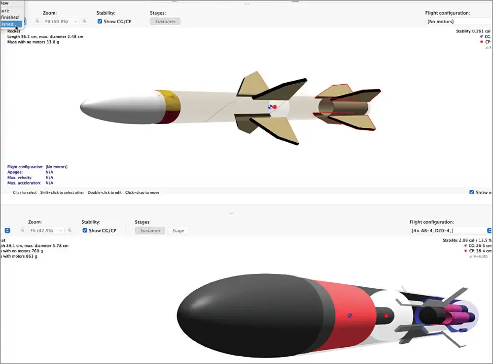
The upcoming parts of this series of articles will explore core rocketry concepts in greater detail, including thrust-to-weight ratio, fin shape and sizing, CG and CP, stability margin, aerodynamics, drag, and structural as well as material considerations. The series will also cover several practical aspects involved in designing a stable, efficient, and flight-ready rocket system. Fig. 1 shows the model rocket design simulator.

Note. Readers interested in discussing ideas, sharing designs, or contributing to the development process can connect using the LinkedIn QR code provided below.
The system is currently in the simulation stage, so not all components are required at this time. However, the final components needed for the design are listed in the Bill of Materials Tables 1 and 2.
| Table 1 Rocket Body | |||
| Category | Component | Specification | Recommended Range/Notes |
| Structure | Body tube | 3D-printed body tube or standard market-available part | Diameter and length as per the selected design specifications and part number |
| Structure | Nose cone (dome) | 3D-printed (PLA/PETG) or standard online-store available part | Specifications should match the selected design and best-fit part number obtained during simulation |
| Structure | Fins | Three fins | Fin dimensions and shape as per simulation and stability requirements |
| Structure | Model rocket engine | Estes C6-5/ES1507 rocket engine or custom-designed rocket engine | Select the rocket engine according to the model rocket design requirements |
| Structure | Launch lug | Small tube | Inner diameter: 5mm–8mm, mounted in proper alignment with the rocket body |
| Structure | Nose weight | Steel or lead weight | Adjusted to shift the centre of gravity (CG) forward for better stability |
| Table 2 Rocket Electronics | |||
| Category | Component | Function | Quantity |
| Flight computer | IndusBoard Coin | IndusBoard Coin with stabilisation and flight computer firmware | 1 |
| Fin controller | Servo motor | Micro gear servo motor for model rocket fin control | 3 |
| Power | 3.7V Li-Po battery | Li-Po battery for rocket circuitry power supply | 1 |
| Communication | Telemetry module | Module for remote rocket data transmission | 1 |
| Video | FPV camera | Camera for rocket launch and in-flight video transmission | 1 |
| Altitude sensing | BME280 | Sensor for measuring air pressure, altitude, and temperature around the rocket | 1 |
| Motion sensing | MPU6050 gyro and accelerometer sensor | Sensor for orientation and acceleration data measurement | 1 |
Designing
When designing a rocket, there are a few key aspects to consider. Before discussing them, however, it is first necessary to finalise the tools used to design and simulate the rocket. There are many paid and open source tools and platforms available for rocket design. This system uses open source platforms for both design and simulation, such as OpenRocket and RASAero. Both platforms are open source and supported by strong communities. This approach aligns with the objective of keeping the rocket system design freely accessible, allowing designers to learn, build, and contribute to the rocketry ecosystem in India. The tools can be installed using the links below:
• RASAero
After downloading and setting up the platforms, the next step is the design phase. The process is carried out step by step, understanding the key design rules and applying them while designing each rocket component.
EFY note. In rocket design, for stable flight, the CG should always be positioned ahead of the CP. CG>CP.
The distance between the CG and CP is known as the stability margin, and for most model rockets, it is recommended to keep it between 1 and 2 calibres for safe and stable flight.
Rocket design involves several important aspects, such as nose cone design, body tube selection, multi-stage rocket configuration, fin design, servo-based fin control, rocket engine selection, and flight simulation.
Nose design
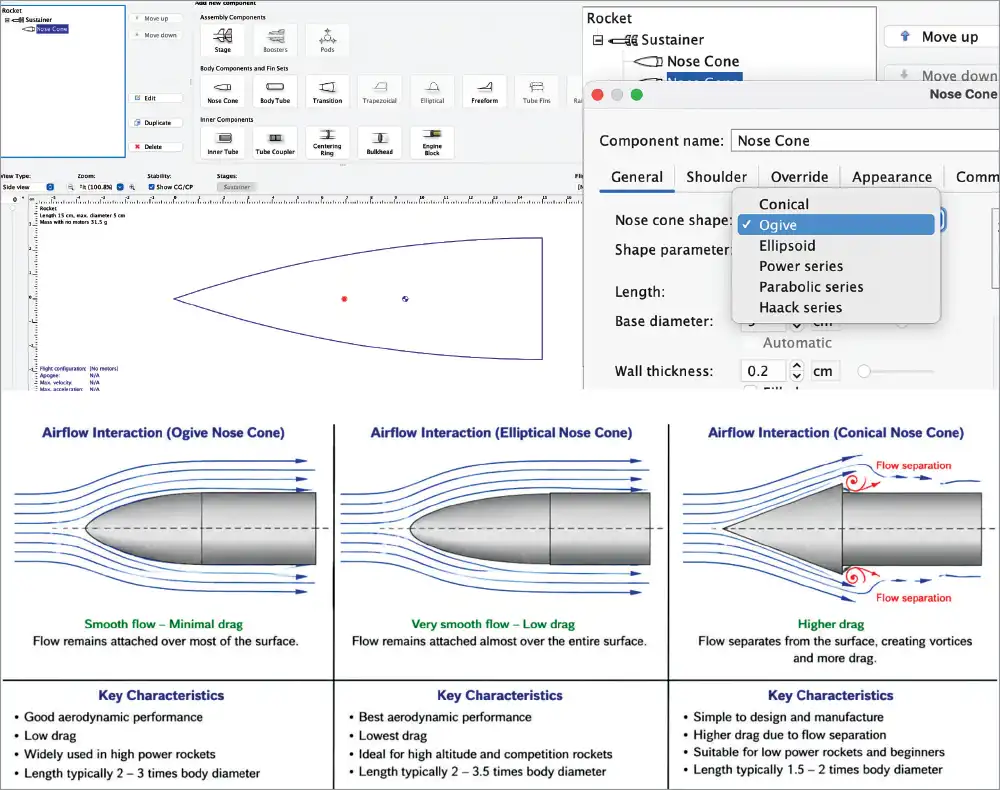
The design process in OpenRocket begins with the topmost part of the rocket, known as the nose cone. Rocket nose cones are generally available in three common forms: Ogive, Elliptical, and Conical. In OpenRocket, a library of standard rocket components is already available, and these parts can be commercially sourced with ease. However, if a customised component is required, the specifications of each part can be modified according to the design requirements. The customised parameters can then be exported as CAD files for manufacturing using CNC machining, 3D printing, or other additive manufacturing processes.
The nose cone shape significantly affects the aerodynamic performance and drag characteristics of the rocket. Fig. 2 shows the nose cone configuration and aerodynamic comparison in OpenRocket. It illustrates different nose cone profiles, along with their airflow interaction, drag characteristics, flow separation behaviour, and suitability for different rocket applications. For more details, refer to: https://tuengr.com/V13/13A13J.pdf.
The body tube
Once the nose cone design is understood, the next important part of rocket design is the body tube. The body tube serves as the main structural section of the rocket, housing all major components, including the rocket motor, electronics, parachute system, payload, and wiring. Designing the body tube is not simply about creating a cylindrical structure. It directly affects the rocket’s stability, aerodynamic drag, structural strength, and internal component arrangement.
One of the most important rules when designing the body tube is maintaining a proper length-to-diameter ratio. In most model rockets, the recommended ratio is:
Length/diameter=10 to 50
This means that if the rocket body diameter is 50mm, the total body length should ideally be between 500 mm and 1000 mm. If the rocket is too short, it may become unstable during flight, while an excessively long rocket can introduce structural bending, additional weight, and higher aerodynamic drag.
The diameter of the body tube mainly depends on the size of the motor, parachute system, and onboard electronics. For most beginner and intermediate model rockets, a diameter between 40 mm and 60 mm is commonly used.
Along with diameter, wall thickness is also important. A thicker body increases structural strength but also adds unnecessary mass, reducing flight efficiency.
Another critical aspect is the internal arrangement of components. The rocket motor is generally placed at the rear section, the electronics bay is positioned near the centre, and the parachute system is usually located toward the front section of the body tube. Proper component arrangement is necessary to maintain the correct centre of gravity and ensure stable flight behaviour.
From an aerodynamic perspective, the body tube surface should be smooth and properly aligned with the nose cone and fins. One important parameter in rocket staging is the mass ratio, given by:
Mass ratio=m0/mf
where m0 is the initial mass and mf is the final mass after fuel consumption. A higher mass ratio generally improves performance and altitude capability, but it also increases structural and design complexity.
Multi-stage rocket
In multi-stage systems, proper alignment between stages becomes extremely important. Even small angular misalignments can destabilise the rocket during separation or ignition. The timing of stage ignition is also critical. Delayed ignition can cause a loss of momentum, while premature ignition can result in structural damage to the rocket.
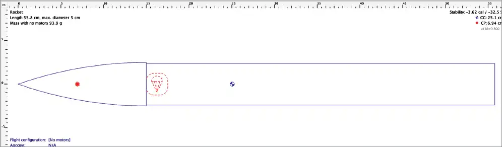
Another important challenge in multi-stage rockets is that the centre of gravity changes dynamically during stage separation. Therefore, stability must be ensured not only before launch but also after each stage separates during flight. Fig. 3 shows an initial model rocket system design created in OpenRocket, showing the nose cone, body tube, CG, and CP.
Fin design
After the body tube, one of the most important parts of rocket design is the fin system. Fins are responsible for stabilising the rocket during flight and helping it maintain direction. The main purpose of fins is to move the CP behind the CG, allowing the rocket to naturally align itself with the direction of airflow during flight. Because of this, fin size, shape, placement, thickness, and alignment become extremely critical for rocket stability.
One of the first rules in fin design is choosing the number of fins. Most model rockets use either three or four fins, but three fins are generally preferred because they provide good stability with lower aerodynamic drag and reduced weight. Using too many fins increases drag unnecessarily, while using very few fins may reduce stability.
The fin size is generally determined relative to the rocket’s body diameter. A common design rule is:
Root chord=1 to 1.5×body diameter
Fin height=1 to 2×body diameter
Tip chord=0.3 to 0.6×root chord
These ratios help maintain a balance between stability and drag. Oversized fins increase drag and reduce altitude, while undersized fins may not provide enough stabilisation force.
Fin placement is also very important. Fins are generally mounted at the extreme rear of the rocket because placing them farther back increases stability by shifting the centre of pressure rearward. Even small alignment errors in fins can create unwanted rotational torque, causing the rocket to spiral or drift during flight.
The thickness of the fins must also be chosen carefully. Thin fins reduce drag but may bend or break under aerodynamic loads. Thick fins improve strength but add weight and drag. For most model rockets, fin thicknesses between 2 mm and 5 mm work well, depending on rocket size and material.
Servo control of the fin
In servo-controlled fin systems, the flight controller continuously reads data from sensors such as accelerometers and gyroscopes and adjusts the fin angles to correct the rocket’s orientation. One important rule in servo fin control is limiting the fin deflection angle. Large fin angles create excessive drag and instability. Most active control systems keep fin movement within:
Fin deflection angle≈±5° to ±15°
Rocket engine
The rocket engine is the propulsion system that generates thrust to lift the rocket against gravity. It works on Newton’s Third Law, where high-speed gases are expelled from the nozzle to produce a force in the opposite direction.
The thrust generated by the engine is given by:
F=ṁVe+(Pe–Pa)Ae
where ṁ is the mass flow rate of exhaust gases, Ve is the exhaust velocity, Pe is the exhaust pressure, Pa is the atmospheric pressure, and Ae is the nozzle exit area.
One of the most important rules while selecting a rocket motor is maintaining a proper thrust-to-weight ratio:
Simulation
The next step is to simulate the rocket and analyse the output to determine whether any fine-tuning is required in the design. From the simulation graphs, important parameters such as altitude, velocity, acceleration, stage ignition, recovery deployment, and overall rocket stability can be studied. The altitude graph shows the maximum height reached, while the velocity and acceleration graphs help analyse motor performance and flight behaviour. Stability analysis verifies proper CG and CP positioning for safe flight.
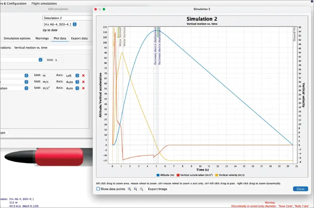
After satisfactory simulation results are obtained, the rocket parts can be assembled, and the control and telemetry code can be uploaded to the IndusBoard Coin for testing and flight operation. Fig. 4 shows OpenRocket flight simulation result displaying vertical motion versus time for the model rocket using a clustered A6-4 motor configuration. The graph displays altitude, vertical velocity, and vertical acceleration during launch, coast phase, apogee, recovery deployment, and descent. The simulation predicts a maximum altitude of approximately 112m with a peak velocity of around 43.9m/s.
EFY note. This is the first part covering rocket design and simulation. The next part will cover the assembly process, circuit connections, flight computer coding, and testing procedure.
To be continued…
Ashwini Kumar Sinha, an IoT and AI enthusiast, is Tech Journalist at EFY.
