
Planning for Using Qorvo QSPICE? Explore its features, latest capabilities, applications, and how this next-generation SPICE simulator helps engineers design faster, more accurate analog, power, and mixed-signal systems.
Every PCB redesign adds development time, increases costs, and delays product launch, making circuit simulation an essential part of modern electronic design. Whether developing a switch-mode power supply (SMPS), motor controller, battery management system (BMS), RF front end, sensor interface, or other mixed-signal electronics, engineers need to verify circuit behaviour, identify design flaws, optimise component values, and minimise hardware iterations well before building a physical prototype. For decades, SPICE (Simulation Program with Integrated Circuit Emphasis) has been the industry standard for circuit simulation.
However, today’s electronic systems combine analog circuits with digital logic, embedded software, switching power stages, and increasingly complex semiconductor devices, often pushing traditional SPICE simulators beyond their practical limits or requiring multiple software tools. To address these challenges, Qorvo introduced QSPICE, a next-generation analog and mixed-signal simulator developed by Mike Engelhardt, the creator of LTspice. QSPICE combines analog simulation with extensive digital logic, C++, Verilog, and Python automation in a single environment, enabling engineers to simulate complex heterogeneous systems more efficiently. Regarding the Model Generator, one engineer wrote: “Generating MOSFET models directly from datasheets saves a huge amount of engineering time.” According to Qorvo, it delivers significantly faster simulation, improved numerical accuracy, greater reliability, and the ability to handle large digital systems without the performance limitations commonly associated with conventional SPICE engines. It is available free of charge for commercial, educational, and personal use.

What is QSPICE?
QSPICE is a schematic capture and circuit simulation platform designed primarily for analog, power electronics, RF, and mixed-signal applications. Instead of simply analysing isolated analog circuits, it allows engineers to simulate complete electronic systems where analog circuits interact with digital logic, firmware algorithms, semiconductor switching devices, and behavioural models.
The simulator combines a high-performance SPICE engine with modern schematic capture, allowing users to create, simulate, debug, and optimise circuits within one integrated environment. It supports traditional SPICE analyses while extending simulation capabilities through native C++ and Verilog compilers, enabling behavioural modelling that would otherwise require external tools. Engineers can also automate repetitive simulations and data analysis using Python, making QSPICE suitable for design exploration and optimisation workflows.
One of the software’s defining characteristics is its focus on mixed-mode simulation. Rather than treating analog and digital circuits separately, QSPICE enables designers to simulate them together, helping identify interactions between power stages, embedded controllers, logic devices, and analog front ends before hardware is fabricated. This reduces design iterations while improving confidence in system-level performance.
Another significant differentiator is the built-in Model Generator, introduced as a major enhancement in 2025. Engineers can now create simulation-ready MOSFET, JFET, and diode models directly from datasheet information in minutes instead of manually extracting dozens of SPICE parameters, a task that traditionally required many hours of engineering effort.
Why QSPICE matters to design engineers
Modern electronic products increasingly combine multiple engineering disciplines, with systems such as EV chargers integrating high-voltage power electronics, digital control algorithms, embedded firmware, gate-driver circuits, feedback control loops, protection circuitry, and communication interfaces. Traditionally, these subsystems often required separate simulation environments, making system-level verification more complex. A user appreciated the behavioural modelling capability:”Having C++ built into the simulator changes what you can model. It opens possibilities that were difficult with conventional SPICE.”
QSPICE brings them together in a single platform, enabling engineers to analyse interactions before hardware development. Power electronics designers can evaluate MOSFET switching, converter efficiency, startup transients, gate-drive timing, feedback compensation, fault conditions, and thermal behaviour using behavioural models, while embedded system developers can verify how digital logic interacts with analog circuitry, helping identify integration issues early in the design cycle.
The key features include:
- High-performance SPICE engine: Delivers faster simulation, improved convergence, higher numerical accuracy, and greater reliability, especially for switching power supplies and large nonlinear circuits.
- Massive digital logic support: Simulates large digital logic designs alongside analog circuitry with minimal performance loss, making it suitable for complex mixed-signal systems.
- Native C++ behavioural modelling: Includes a built-in C++ compiler, enabling engineers to develop behavioural models, control algorithms, proprietary device models, and custom functions more easily than using complex SPICE equations.
Advanced Modelling, Automation, and Verification Features
QSPICE extends mixed-signal simulation with Verilog support, allowing digital hardware descriptions to be integrated directly into analog simulations for complete system-level verification within a single environment. It is well suited for applications such as digital controllers, battery management algorithms, motor-control logic, protection systems, sensor processing, and power management.
The software also includes an integrated Model Generator that automatically creates MOSFET, JFET, and diode models from datasheet specifications and characteristic curves, significantly reducing the time required to build accurate semiconductor models. For design automation, Python integration enables engineers to automate simulation runs, parameter sweeps, waveform analysis, report generation, and optimisation workflows, improving productivity during design exploration. One engineer commented: “It converges much faster than I expected, especially on switching power supplies. Large simulations finish noticeably quicker.”
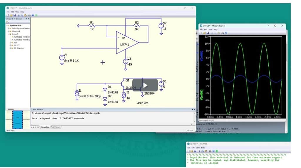
QSPICE further enhances usability with a publication-quality waveform viewer for measurements, annotations, waveform comparisons, and exporting professional graphics, while third-party SPICE model compatibility allows reuse of existing component libraries, simplifying migration from other simulators. Another major advantage is its free commercial licensing, providing the full feature set for commercial, educational, and personal use without licence restrictions or recurring subscription costs.
What can engineers do with QSPICE?
QSPICE enables engineers to simulate complete analog, digital, and software-driven systems, making it suitable for both circuit-level validation and system-level design. Key applications include:
- Power electronics: Design and optimise AC-DC/DC-DC converters, SMPS, PFC circuits, flyback, buck, boost, resonant, and isolated power supplies by analysing startup behaviour, efficiency, switching losses, ripple, stability, and control-loop performance.
- Battery management systems (BMS): Model battery packs, charging circuits, balancing networks, protection stages, and fault conditions to evaluate charging profiles, voltage protection, current limiting, and thermal behaviour.
- Motor drives: Simulate BLDC, PMSM, and industrial motor drives by analysing PWM generation, gate drivers, sensing circuits, inverter efficiency, switching sequences, dead-time, and protection mechanisms.
- Mixed-signal embedded systems: Verify interactions between analog front ends, sensors, microcontrollers, digital interfaces, and power management in applications such as IoT devices, industrial controllers, smart appliances, medical equipment, and data acquisition systems.
- Semiconductor device evaluation: Analyse MOSFETs, diodes, JFETs, and other devices using manufacturer models or automatically generated models derived from datasheets.
- RF and analog circuits: Simulate circuit-level RF designs including RF power amplifiers, LNAs, oscillators, bias networks, impedance-matching circuits, and analog filters alongside digital control and power circuitry.
- Behavioural modelling: Develop custom C++ and Verilog models for digital controllers, battery algorithms, motor-control firmware, sensors, communication interfaces, proprietary semiconductor behaviour, and protection logic.
Simulation Capabilities
QSPICE supports a comprehensive range of analyses for professional circuit and mixed-signal design:
- DC Analysis: Determines operating points, bias voltages, and currents for regulators, amplifiers, reference circuits, and bias networks.
- AC Analysis: Evaluates gain, phase, bandwidth, stability, loop response, and filter characteristics for amplifier, compensation, and filter design.
- Transient Analysis: Simulates time-domain behaviour such as converter startup, PWM operation, MOSFET switching losses, motor startup, battery charging, inrush current, and fault conditions.
- Parameter Sweeps: Automatically varies component values to optimise inductors, capacitors, switching frequency, and control-loop compensation.
- Temperature Analysis: Examines the impact of temperature on semiconductor performance, bias stability, converter efficiency, and protection circuits.
- Monte Carlo Analysis: Predicts design robustness and manufacturing yield by simulating component tolerances and parameter variations.
- Behavioural Simulation: Uses native C++ and Verilog support to model advanced control algorithms, digital power management, and complex system behaviour beyond conventional SPICE equations.
Where is QSPICE used?
Originally developed for power electronics, QSPICE has evolved into a versatile simulator for a broad range of electronic design applications. It is widely used in power electronics for designing and optimising SMPS, AC-DC and DC-DC converters, inverters, UPS systems, and EV chargers. In automotive electronics, it supports the development of battery management systems (BMS), motor controllers, automotive power supplies, LED lighting, sensor interfaces, and electronic control units (ECUs). It is also well suited for renewable energy applications, including solar inverters, energy storage systems, grid converters, MPPT controllers, and battery chargers.
Beyond these sectors, QSPICE is used in industrial automation to design PLC power supplies, servo drives, variable-frequency drives (VFDs), industrial sensors, and factory automation equipment. In consumer electronics, it enables simulation of laptop adapters, smartphone chargers, USB Power Delivery (PD) systems, home appliances, audio amplifiers, and smart-home products. Semiconductor manufacturers can use it to evaluate devices, validate reference designs, and generate SPICE models for customers, while its free licensing for both commercial and educational use has made it increasingly popular in research and academia for teaching analog electronics, power electronics, and circuit simulation.
What’s new in recent QSPICE releases?
QSPICE follows a continuous development model with frequent feature updates instead of annual software releases, allowing new capabilities and usability improvements to be delivered regularly. A major addition is the Model Generator, introduced in 2025, which automatically creates MOSFET, JFET, and diode models from datasheet characteristics, significantly reducing the time needed to build accurate device models. Recent versions have also expanded Python integration for automating simulations, parameter sweeps, waveform analysis, and optimisation workflows, while Verilog support and mixed-signal performance have been further refined for faster and more reliable analog-digital co-simulation. Usability has also improved through enhancements to the schematic editor, waveform viewer, and compatibility with third-party SPICE libraries, with many updates driven by feedback from the QSPICE user community. Major enhancements include:
- Model Generator (2025): Automatic MOSFET, JFET, and diode model generation from datasheets.
- Expanded Python support: Automation of simulations, post-processing, optimisation, and parameter sweeps.
- Improved Verilog and digital simulation: Faster mixed-signal simulation with better analog-digital interaction.
- Enhanced schematic editor: Better navigation, symbol management, and Symbol/IP Browser support.
- Optimised waveform viewer: Faster analysis of large datasets with publication-quality graphics.
- Community-driven updates: Regular improvements to usability, simulation accuracy, device models, and third-party SPICE compatibility.
QSPICE vs LTspice
Since QSPICE was developed by Mike Engelhardt, the creator of LTspice, engineers naturally compare the two simulators. While both are powerful SPICE-based tools, QSPICE has been designed as a next-generation platform that addresses many limitations of traditional SPICE simulators, particularly for modern mixed-signal and power electronics applications.
| Feature | LTspice | QSPICE |
| Developer | Analog Devices | Qorvo |
| Core focus | Analog simulation | Analog + Mixed-signal simulation |
| Digital logic | Basic | Large-scale digital logic support |
| Native C++ compiler | No | Yes |
| Verilog compiler | Limited | Integrated |
| Python scripting | No | Yes |
| Model Generator | No | Yes |
| Third-party SPICE models | Yes | Yes |
| Commercial use | Free | Free |
| Platform | Windows, macOS | Windows (official) |
For engineers designing conventional analog circuits, LTspice remains a mature and widely adopted choice with a vast component library. However, QSPICE targets modern electronic systems where analog circuits coexist with digital control, behavioural models, and software-defined functionality. Features such as native C++, Verilog integration, Python automation, and the built-in Model Generator make it particularly attractive for power electronics, embedded systems, and mixed-signal applications.
What can you do with the free version?
One of QSPICE’s biggest differentiators is its completely free licensing model. Unlike many commercial EDA tools, it does not offer a feature-limited free edition or require a paid professional version—all users receive the complete software with unrestricted commercial, educational, and personal use. There are no subscription fees, recurring licence costs, or artificial limitations, making it an attractive option for startups, independent consultants, universities, research organisations, and large enterprises alike. The free version includes:
- Unlimited schematic capture
- Full analog and mixed-signal simulation
- Native C++ and Verilog compilers
- Python integration
- Built-in Model Generator
- Publication-quality waveform viewer
- Third-party SPICE model support
- Continuous software updates
There are no:
- Node or component limits
- Simulation-time restrictions
- Disabled professional features
- Watermarks
- Commercial-use restrictions
QSPICE is also designed to fit seamlessly into existing SPICE workflows. It supports SPICE netlists, subcircuits (.SUBCKT), library files (.LIB), model files, Verilog modules, C++ models, and Python scripts, while allowing engineers to import third-party SPICE models from semiconductor vendors. This enables organisations to reuse existing simulation libraries instead of rebuilding models, simplifying migration from other SPICE-based design environments.
System requirements and supported platforms
QSPICE is lightweight compared with many commercial EDA suites and runs comfortably on most modern engineering workstations.
| Requirement | Recommended |
| Operating System | Windows 10 or Windows 11 (64-bit) |
| Processor | Multi-core Intel Core, AMD Ryzen, Xeon, or EPYC |
| Memory | Minimum 8 GB; 16 GB or more recommended |
| Storage | SSD with several GB of free space |
| Graphics | Dedicated GPU optional; not required |
| Internet | Required for download, updates, documentation, and community resources |
For large mixed-signal designs involving extensive waveform storage or behavioural models, higher RAM capacities and fast NVMe SSDs improve performance significantly.Although some users successfully run QSPICE under compatibility layers such as Wine, Qorvo officially supports Windows.
Getting started with QSPICE
Engineers new to QSPICE can begin designing circuits within minutes.
A typical workflow includes:
- Download QSPICE from Qorvo’s Design Hub.
- Install the software.
- Create a new schematic.
- Place components using the schematic editor.
- Import vendor SPICE models if required.
- Configure simulation parameters.
- Run DC, AC, or transient analyses.
- Examine waveforms and performance metrics.
- Optimise component values using parameter sweeps.
- Export plots or automate further studies using Python.
Qorvo also provides QuickStart videos, documentation, application notes, and an active community forum to help new users become productive.
To achieve accurate and efficient simulations in QSPICE, engineers should begin with validated component models, preferably those provided by semiconductor manufacturers, as they closely represent real device behaviour. When third-party SPICE models are required, they should be verified before being incorporated into critical designs. It is also good practice to develop and validate individual circuit blocks before combining them into complete systems, making it easier to isolate errors and improve convergence. For digital control functions, behavioural models are often more efficient than creating complex transistor-level implementations. Large projects can be managed more effectively by organising frequently used sections into reusable subcircuits. Engineers should perform parameter sweeps early in the design cycle to identify robust component values and use Python scripting to automate repetitive optimisation tasks. When simulating switching power supplies or other highly nonlinear circuits, reviewing convergence settings can significantly improve simulation stability and reduce runtime.
Common Mistakes to Avoid
Even experienced designers can encounter simulation issues if basic modelling practices are overlooked. One of the most common mistakes is relying on inaccurate or unverified semiconductor models, which can produce misleading results. Engineers should also account for parasitic inductance, capacitance, and resistance rather than assuming ideal components throughout the design. Ignoring temperature variations can lead to unrealistic performance predictions, particularly in power electronics and automotive applications. Another frequent error is attempting to simulate an entire complex system before validating individual functional blocks, making debugging unnecessarily difficult. Similarly, combining third-party model libraries without compatibility checks may introduce convergence problems or incorrect behaviour. Finally, simulation results should always be validated through laboratory testing, as successful simulation alone does not guarantee reliable or manufacturable hardware.
Advantages and Limitations
QSPICE combines a high-performance simulation engine with a completely free licensing model for both commercial and educational use. It offers fast, reliable simulation with excellent convergence, especially for analog, power electronics, and mixed-signal designs. Native support for C++ behavioural modelling, Verilog simulation, and Python scripting enables advanced design automation, while the built-in Model Generator and waveform viewer simplify device modelling and result analysis. Regular updates further strengthen its capabilities for modern electronic design.
As a relatively new EDA platform, QSPICE still has some limitations. It officially supports only Windows, has a smaller built-in device library than LTspice and some commercial tools, and a comparatively smaller user community with fewer learning resources. It also lacks an integrated PCB layout environment, and its advanced C++ behavioural modelling features may require a learning curve. However, these limitations are expected to reduce as the platform and its ecosystem continue to mature.
Should Engineers Use QSPICE?
QSPICE has emerged as one of the most capable free circuit simulators for analog, power electronics, and mixed-signal design. Its high-speed simulation engine, strong convergence, unrestricted commercial licensing, native C++ and Verilog support, Python automation, and advanced behavioural modelling make it suitable for both individual engineers and professional design teams.
The platform is well suited for analog and power electronics design, motor control, battery management systems, automotive electronics, industrial automation, embedded systems, research, and engineering education. Engineers relying on extensive legacy component libraries may still prefer LTspice or commercial EDA tools for some projects. However, for new mixed-signal designs and software-assisted behavioural modelling, QSPICE offers capabilities beyond many traditional free SPICE simulators.
More than a next-generation SPICE simulator, QSPICE reflects the industry’s shift toward integrated analog, digital, and software-defined system design. By combining high-performance analog simulation with native digital modelling, behavioural programming, Python automation, and unrestricted commercial licensing, it delivers a modern, professional-grade EDA environment at no cost. Although still evolving, its feature set already makes it a strong choice for developing power electronics, embedded control systems, mixed-signal products, and other advanced electronic designs. For engineers and organisations seeking a feature-rich, free circuit simulator, QSPICE is a compelling addition to the design workflow.
For more information, click here.