


Presented here is a project based on Global Positioning System (GPS) and ATmega328P-PU microcontroller to measure the distance between two points using Haversine formula. This GPS distance meter can be used for a thermal power-plant patrolling/inspection or any other application where large distance measurement is required.
For example, in the thermal power plant industry, a patroller is required to take measurements for laying out a new route, replacement/shifting of old routes or extension of pipelines deep inside the dyke. These activities are carried out quite often, and each measurement requires two persons for holding a large measuring tape. Demand for a GPS distance meter starts here.
Hardware requirement for GPS Distance Meter
You need Arduino with an internal 8MHz clock, GPS receiver with serial data port, microSD memory card, 16×4 LCD, pushbutton switches and a few other components.

Circuit and working
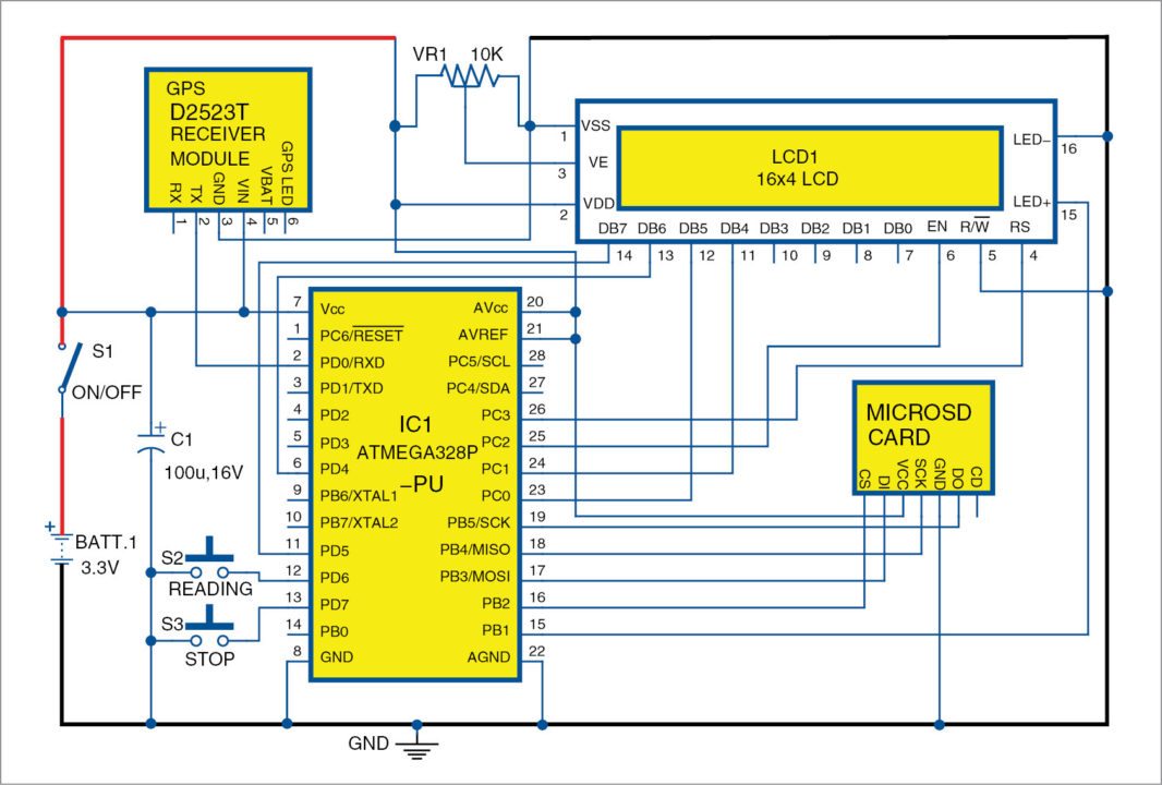
Circuit diagram of the GPS distance meter is shown in Fig. 1. To make the circuitry simple and less power consuming, the 16MHz resonator/crystal and associated pico capacitors on Arduino board are not used. Arduino is programmed on plain ATmega328P-PU with an internal 8MHz clock. The circuit is powered off a 3.7V lithium-ion battery.
D2523T GPS receiver module used here requires between 3V and 3.6V DC supply and takes around 40mA current. The module has two LEDs on top and a green LED for pulse per second (PPS).

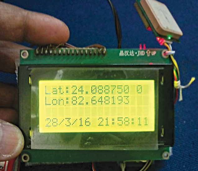
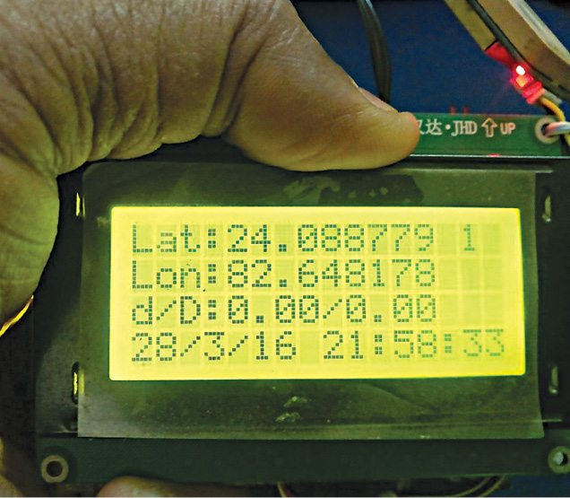
Since the pipelines are all in the open, connection with GPS satellites that are on low-Earth orbit are almost instant. After the device is switched on, cold start of this GPS device takes less than 20 seconds. You can check this from the continuous flashing of PPS green LED on the GPS receiver. Immediately, latitude and longitude readings along with date and time will flash on the LCD panel.
Press switch S2 to start measurement reading, and mark the initial reading. Now, move to a desired location along with this assembly for taking distance reading. Distance measurement values will flash on the third line of the LCD and at the same time all readings including serial no, date, time, latitude, longitude, dist_inst (d) and dist_total(D), will be dumped into a text file, which will be stored automatically on the microSD memory card (8GB, 16GB and so on) attached to the device.
Latitude and longitude readings are taken up to six decimal points for calculations. Double precision variable is used for the same.
Chances of error may be to the tune of 2.5 metres to 10 metres. Under the open sky, where GPS satellites are easily located, the error is minimum. On a cloudy day, sighting of GPS satellites may take a longer time. So before pressing S2, wait for a while until values of latitude and longitude get stabilised.
Software
The code is written in Arduino programming language. ATmega328P is programmed using Arduino IDE software. Select the correct board from Tools Board menu in Arduino IDE and burn the program (sketch) through the standard USB port in your computer.
Arduino Uno has an external clock circuitry with a 16MHz resonator and two picofarad capacitors. You can use Arduino Uno board directly, but to get it programmed on an 8MHz internal clock is rather challenging. For that you need an unprogrammed ATmega328P chip that has never been programmed with 16MHz external resonator. Because once it is programmed with an external clock, it will never go back to 8MHz internal clock mode.
Read ‘Arduino as AVR Programmer’ article for programming it with 8MHz internal clock. You can get it at https://www.electronicsforu.com/electronics-projects/hardware-diy/arduino-avr-programmer
An advantage of 8MHz internal clock is that it is easy to make connections on a piece of veroboard. Besides, its power consumption is not even 10mA on 3.3V supply.
Various operations are implemented in the code, and following header files are included in the library. Each header file has definitions for the library, while the source file has the actual code.
LiquidCrystal.h for LCD panel. This library allows the Arduino board to control LCDs based on Hitachi HD44780 (or a compatible) chipset, which is found on most text based LCDs. The library works within either 4-bit or 8-bit mode (that is, using four or eight data lines in addition to RS, enable and, optionally, RW control lines).
TinyGPS.h for GPS. TinyGPS is a new Arduino library for parsing NMEA data streams provided by GPS modules.
SPI.h. This is for connecting the SD card. This library allows you to communicate with SPI devices, with Arduino as the master device.
SDFat.h. Arduino SdFat library provides read/write access to FAT16/FAT32 file systems on microSD/SDHC flash cards.
Construction and testing
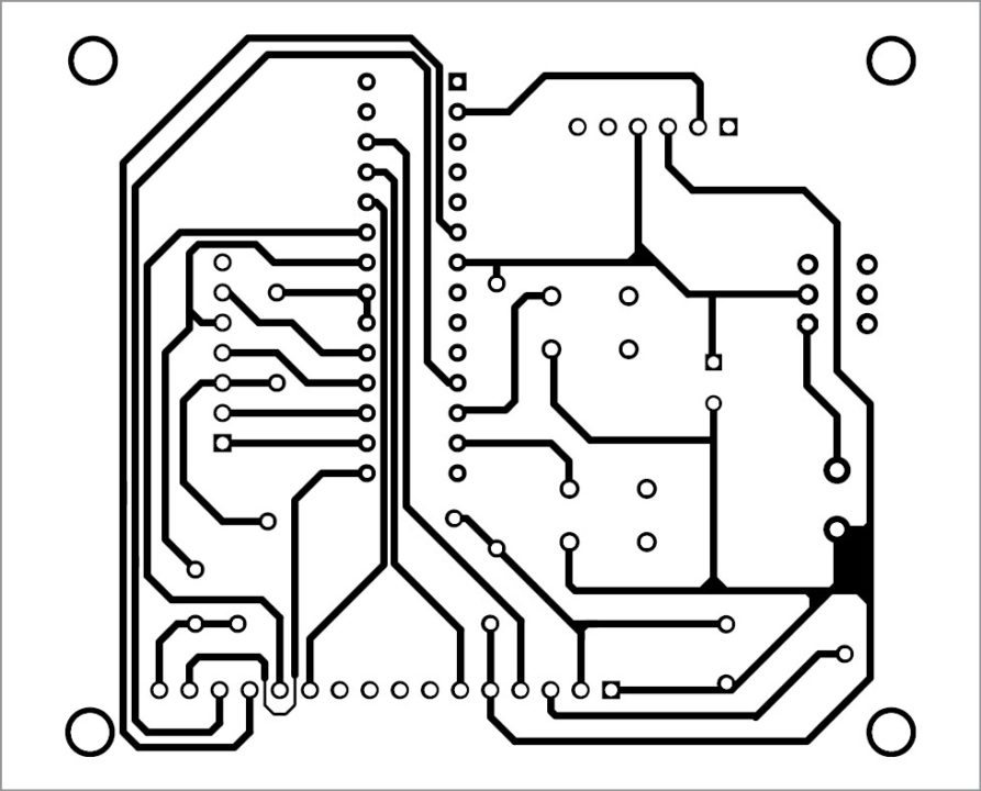
An actual-size PCB pattern for the GPS distance meter circuit is shown in Fig. 2 and its component layout in Fig. 3.
Switch on the GPS receiver and wait till PPS LED on 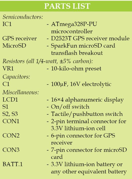 the GPS starts blinking. Soon you will find latitude and longitude values flashing on the LCD. Get the readings stabilised on the LCD.
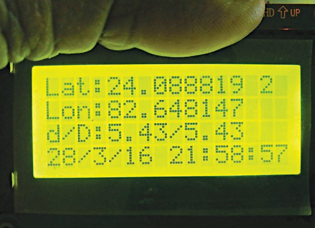
Press S2 and you will get instantaneous distance (d) and total distance (D) values on the third line of the LCD panel. For example, if distance from point A to B is 10 metres and from point B to C is 20 metres, total distance D will be 30 metres. The distance from A to B or from B to C is the instantaneous distance.
To measure the distance from point A to C, press S2 and keep it pressed till you reach point B. Release S2 to stop the measurement; d/D values (instantaneous/overall distance) on LCD will be shown as 10/10. The same values will be stored on the microSD card. Now, press S2 again till you reach point C. Release S2 and note the d/D values. You will see 20/30 on the LCD.
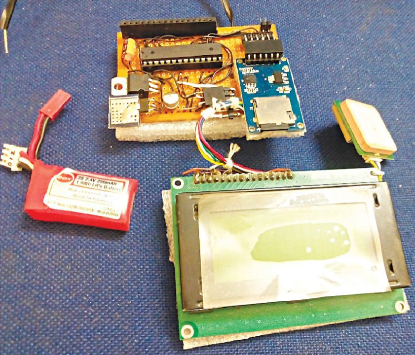
Finally, when all measurement readings are taken, press S3 to close the file and halt the system. Reset Arduino to restart the system. Author’s prototype is shown in Fig. 4.
The log file gets stored on the microSD card. Every time you start the device, it will create a new log file by the names data0.csv, data01. csv, data02.csv and so on as given below:
Sl Date Time Lattitude Longitude Dist. Dist0
0 20/3/16 23:1:18 24.088750 82.648200 0.0000 0.0000
1 20/3/16 23:1:21 24.088750 82.648200 0.0000 0.0000
2 20/3/16 23:1:24 24.088750 82.648200 0.0000 0.0000
3 20/3/16 23:1:29 24.088750 82.648200 0.0000 0.0000
EFY note: The project was tested at EFY Lab on Arduino Uno with an external 16MHz crystal and was found to be working well.
Download The Source Code: CLICK HERE
Download the PCB and component layout PDFs: CLICK HERE
Somnath Bera is an avid user of open source software. Professionally, he is a thermal power expert and works as additional general manager at NTPC Ltd
where we get the components of this project please mention
Sir please send this gps distance meter rate
Kindly elaborate your query.