


To read previous part: click here
In the previous parts of this article, we read about high-speed PCB design, multi-layer PCB design and grounding for electromagnetic compatibility. Let us now look at electrical bonding.
Electrical bonding is a process by which parts in an equipment assembly or sub-systems within a system are connected electrically by their joints or by any low-resistance bonding media. The main purpose of a bond is to make a structure homogenous with respect to the flow of radio frequency (RF) current, so that it would experience minimum barrier as it crosses one surface to the other without developing electrical potential at the crossover point.
To ensure electromagnetic compatibility (EMC) in an equipment or a system, the various components, modules, cable shields, connectors, etc that make up the system need to be connected to a chassis or reference ground via a low-impedance bond that should provide near-zero impedance at all frequencies, or at least over those frequencies for which EMC standards require measurements to be carried out.

Good bonding is required, for example, for mounting line-filter modules on the chassis that serves as a drain for EMI currents, or for connector shells to equipment enclosures to ensure shielding integrity of cable shields that are terminated on these connectors, or for ensuring shielding integrity over seams and joints to avoid leakage of RF energy.
Behaviour of a bond at RFs
At direct current (DC) or power frequencies, bond resistance should be less than one milli-ohm. Even if this is ensured, behavior of the bond at RF can be very different, since parasitic effects set in and the bond is no longer purely resistive. Fig. 21 represents the bond at RF where you can see that, in addition to resistance, there is now self-inductance in series and residual capacitance in parallel.
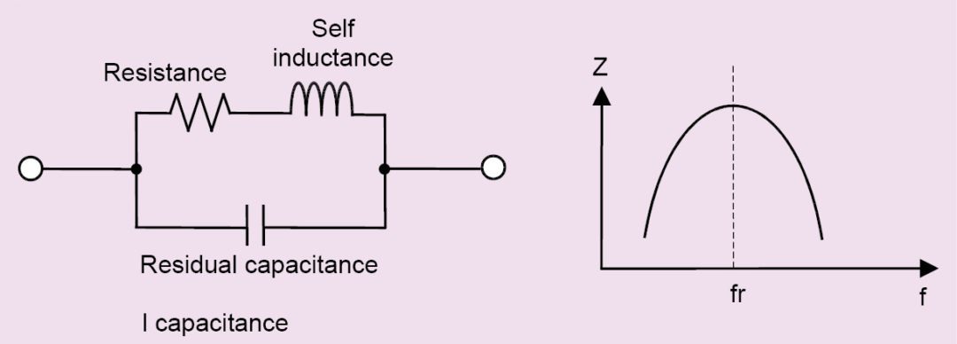
This now becomes a parallel resonant circuit and at its resonant frequency (fr) it exhibits a high impedance. In addition, at higher frequencies, due to skin effect, current tends to flow via the outer periphery of the conductor, and the bond offers a high resistance.
Types of bonding
The intention of bonding is to prevent a voltage difference between the members being joined. To perform effectively at DC or low frequencies, including 50Hz or 60Hz power frequencies, a simple (but durable and permanent) low-resistance joint is adequate.
To accomplish a low DC resistance bond between two adjoining cabinets, bolt holes can be drilled in the adjoining parallel cabinet walls and the two cabinets can be bolted together with star washers at the points of contact between the cabinet walls.
But such a bond is deficient at high frequencies because of higher resistance and inductive reactance. This is more marked where the bond involves dissimilar metals where non-linear junctions can develop at the bonds, leading to the generation of spurious and harmonics, especially under the presence of strong RF fields, causing interference.
To reduce these problems, a radical approach is required if the bond is to work at high frequencies. The most effective method is to split the bonding process into two—mechanical and electrical. Mechanical part of the bond provides only the physical strength to make it robust mechanically, while electrical part of the bond provides low-impedance connectivity to make the bond electrically robust.
Bonds can be broadly classified as direct bonds and indirect bonds. Direct bonding is where specific portions of the surface areas of the members are placed in direct contact by permanent or semi-permanent bonds. Permanent bonds can be achieved by welding, brasing or soldering. Semi-permanent bonds are bolted connections that provide flexibility and accessibility. For satisfactory bonding, the bolt or screw should serve as a fastner, and should maintain a pressure of 85kg/cm2 to 110kg/cm2.
An indirect bond is used in situations where the metal-to-metal contact is not electrically reliable, like for parts that are removed frequently, parts that have relative motion like hinges, parts that use dissimilar metals and parts that are exposed to corrosion. Here, in addition to the primary bond (which provides for the mechanical joint), an indirect bond in the form of straps or jumpers (thick wires) is incorporated (Fig. 22).
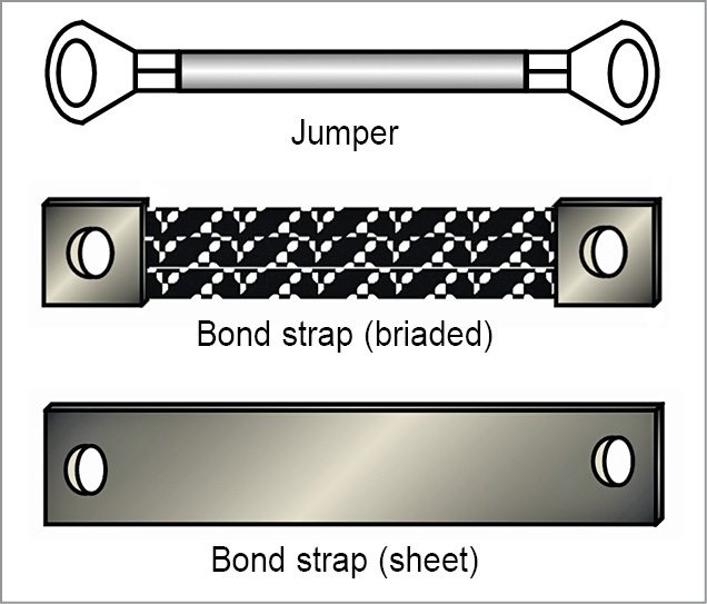
Jumpers are employed in low-frequency scenarios and can be short or stranded conductors, generally round in cross-section. These jumpers, unfortunately, exhibit self-inductance and residual capacitance at high frequencies due to the skin effect. In such cases, special flat braids or sheet-metal straps called bond-straps are used. For bond-straps to work effectively, width-to-thickness ratio should be ten or more, while length-to-width ratio should not exceed five.
Bonding of protective earth wire. In a typical electronics cabinet, a protective earth wire (green or green-yellow wire) is used for safety reasons to connect the cabinet to external earth.
As shown in Fig. 23, this is usually done by providing a bonding terminal—essentially a bolt screwed to position and held in place by a captive nut or a stud welded to the enclosure cabinet, the latter being a better option. While fixing the earth wire, any insulating surface finish (paint or powder coating) is removed from the contact area.
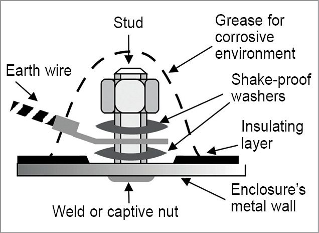
The contact area should be slightly larger than the surface area of the lug. A spiky or shake-proof washer is first put into place to ensure a good lifetime bond. Over this is placed the lug. Another shake-proof washer is then placed over the lug after which the nut is tightened. If the bond is likely to be exposed to moisture or corrosive environment, a coating of paint or grease is applied over the bond.
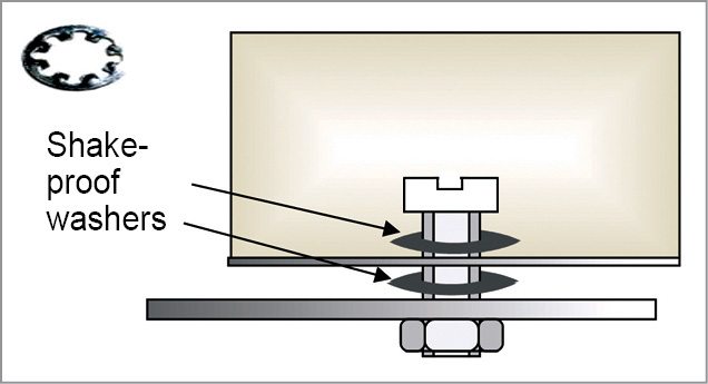
Bonding of internal protective earth wires. Earth conductors of modules housed in non-metallic enclosures, installed inside a cabinet, have to be connected to local ground reference or mounting plates or chassis. In such cases, a captive nut-and-screw arrangement is useful as shown in Fig. 24. The captive nut is welded on the other side of the mounting plate, and the earth conductor with a lug is fixed by a screw that slides through this nut.
Bonding in electronic cabinets. In any electronic cabinet, direct metal-to-metal contacts/bonds give best RF performance since the contact is over the entire surface rather than a single point. For this reason it is imperative to have local RF reference in the form of a metal plate or sheet, and not a single bolt or stub, as shown in Fig. 25.
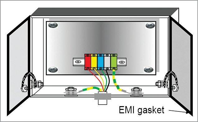
The metal plate exhibits low inductance and, hence, provides low impedance at RF frequencies. All modules having a metal enclosure such as filters, switched-mode power supplies and drives are directly installed on this mounting pate, allowing contact over the entire mating surface.
The plate can be connected to either the protective earth coming from the utility or to a dedicated facility earth, the latter being more useful in severe environment where protective earth may already be polluted. If protective earth has to be extended to the modules via, say, a dual-in-line (DIN) rail-mounted terminal block, then it can be done by a separate wire to comply with requirements of electrical safety standards.
Earthing can be extended to hinged doors by using bond straps (braided or sheet metal). For more effective earthing of metal doors, EMI gaskets can be installed over the mating surface at the periphery.
Bonding screened cables with connectors. Screened cables are many a time used to bring signals from the external world to modules inside a cabinet. When these enter the cabinet, either through a connector or otherwise, their shields need to be connected to the local RF reference (which can be the mounting plate or metal enclosure of the module, or even the PCB reference plane) through a low-RF impedance bond.
When shielded connectors with metal or metal covers such as D-type connectors are used, cable shields need to be bonded to the connector body. The simplest way is to use a semi-circular or saddle clamp. As shown in Fig. 26 (a), the shield is exposed in such a way that the exposed surface area is just a shade greater than the clamp surface area.
Care should be taken that curvature of the clamp matches that of the cable to ensure total contact over the entire mating surface. The clamp, when tightened, exerts a small pressure over the shield. The clamp is then fixed on the connector shell at two points. Since the saddle clamp is semi-circular, it may not provide full 360° and, consequently, the connector can be used in situations where shielding-effectiveness requirements are not that high.
The best way to have a true 360° contact as well as to provide good strain relief is to use a circular metallic connector, where the shield is in contact with the connector outer shell over a full circle and a separate provision is made for strain relief. Such connectors give the best RF performance.
As shown in Fig. 26 (b), the outer shell comes in two parts: one that clamps the cable jacket to provide the necessary strain relief and the other that clamps the exposed shield and connects it to RF reference or the module enclosure. The shield is connected to the metal body of the connector via a special EMI gasket called IRIS compression ring, which is a part of the connector back-shell and encircles the cable at the shield.
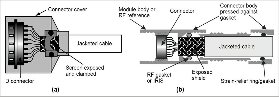
Advantage of using IRIS is that the shield only has to be trimmed and slipped into the connector without disturbing the over-shield braid structure.
Bonding screened cables that have no connectors. In cases where shielded cables do not employ connectors, it is imperative that the shield be bonded to the mounting plate (RF reference) at a point closest to the module or even to the module body itself (which is, in turn, bonded to the mounting plate). There are various methods suggested by manufacturers for bonding the shield to RF reference. Those methods where the exposed shield is bonded to the reference by a separate wire or where shield itself is twisted and bonded to the reference (called pigtails) are generally not recommended since their RF performance is dismal.
Pigtails are typically worse by more than 35dB for frequencies above a few megahertz than other methods. A better method is to employ P-clips, which clamp around the exposed shield and bond to mounting plate (or module body) at a single point. Saddle clamps provide an even better method where the shield is bonded to the clamp, which is, in turn, bonded to the mounting plate at two points.
Conclusion
In the previous and current parts of the article, we have seen various methods of grounding and bonding. These methods are not only important themselves but also contribute in a big way in increasing the efficiency of other design methods to ensure EMC like filtering and shielding.
There is no denying the fact that these measures have to be taken into consideration before going for fixes like filtering and shielding as these are design measures and do not cost much, if taken care of before freezing equipment design. These can further reduce cost of filters and shielding measures by reducing their performance requirements and thus contribute in reducing the overall cost of the equipment.
To be continued…
Chetan Kathalay is working as scientist in Electronics Test and Development Centre, Pune. He is BE in electronics from Nagpur University