


 If you are a space enthusiast and like to look at the stars, chances are you are already familiar with the ISS. The ISS, or International Space Station, revolves around the earth six times each day. If you are interested in the ISS, like the author who is an aerospace engineering student, you will love this ISS Lamp project.
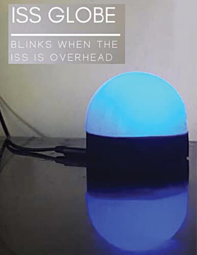
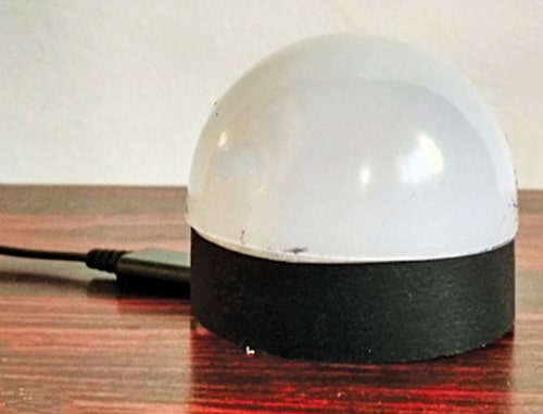
This easy-to-make device is a small hemispherical lamp that gives a mild glow when connected to a power supply. But when the ISS passes over its location, the lamp starts blinking for about 30 seconds to a few minutes. The author’s prototype is shown in Fig. 1.
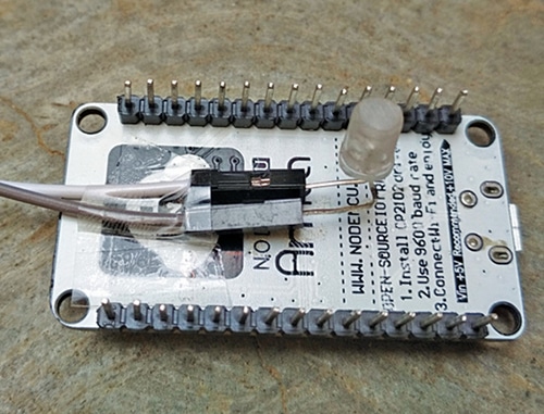
All you need to make this ISS Lamp project is a node microcontroller (nodeMCU), a 5mm LED, a bit of wire, thick cardboard to make the stand, and the globe to work as a lamp.

For testing this project, you need Adafruit IO and IFTTT platforms. Adafruit IO is a cloud service designed for users to display, respond, and interact with their data safely and securely in the cloud. IFTTT derives its name from the programming conditional statement “if this, then that” and is a software platform that connects apps, devices, and services from different developers to trigger one or more automations involving them.
To make the project, first set up Adafruit IO and then install the IFTTT app, which is easily available for free on the internet.
Setting Up Adafruit IO
To set up Adafruit, open the website io.adafruit.com, create an account, and login. Then follow the steps mentioned below:
- Click on Feeds in the top bar and select New Feed, as shown in Fig. 2.
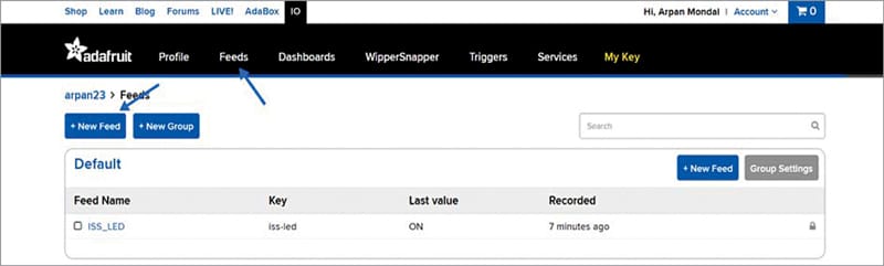
Fig. 2: Step 1 to create a feed on Adafruit Give a name to your feed. You may use the same name that has been used for the project (see Fig. 3), which is ISS_LED, as this will make the programming easier.
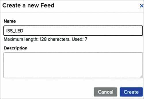
Fig. 3: Step 2 to create a feed on Adafruit - Click on Dashboards in the top bar and select New Dashboard, as shown in Fig. 4. Give it the same name as your feed, that is, ISS_LED.
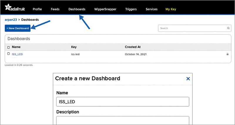
Fig. 4: Creating a dashboard - Click on the dashboard you created and select the gear icon on the right (see Fig. 5).
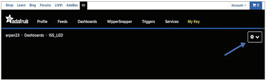
Fig. 5: Creating a new block - Then select ‘Create a new block’ and click on the toggle switch (see ON in Fig. 6).
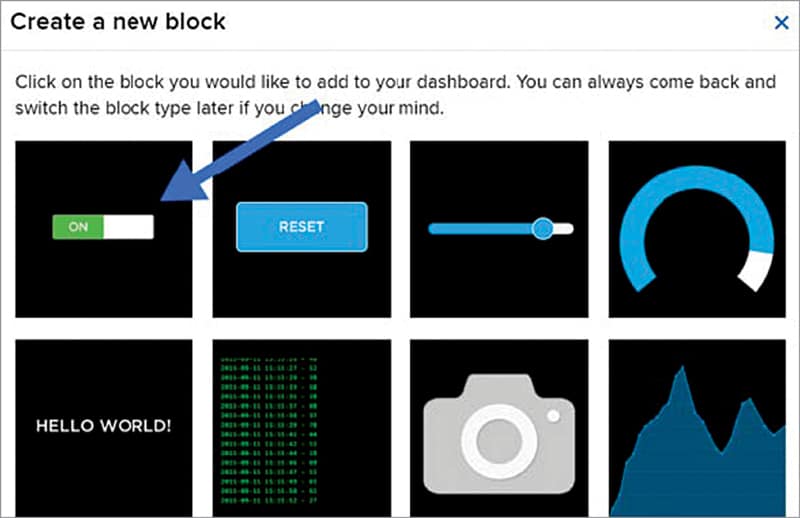
Fig. 6: Selecting toggle switch as your block - Select your feed name (ISS_LED in this case) in the popup window and click on Next Step. In the next window, don’t change anything, just click Create Block.
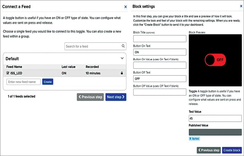
Fig. 7: Configuring the toggle switch - Once your block has been created, click on My Key in the top bar (see Fig. 2) and note down your Username and Active Key, which is unique to your project. Do not share these with anyone as they may mess up your project (see Fig. 8).
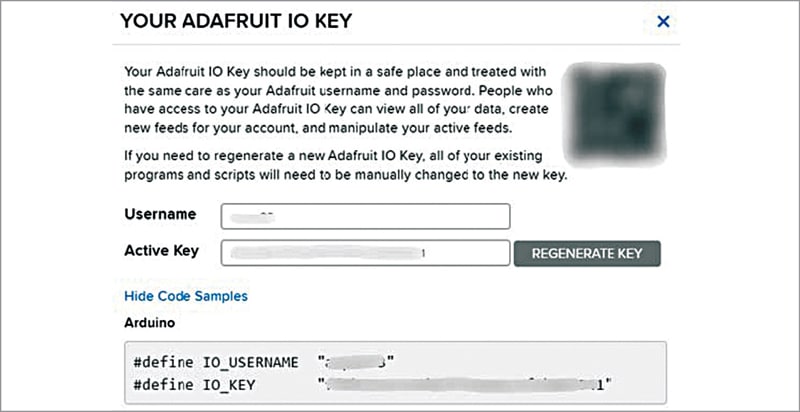
Fig. 8: Entering your Adafruit active key
Now that the Adafruit set up has been completed, you can set up IFTTT after downloading the IFTTT app (or you can just use the desktop site).
Setting Up IFTTT
To set up IFTTT, follow the steps below:
1. Click on Create (bottom left in Fig. 9) and select If This box. Search Space in the search bar and click on it. Click on ‘ISS passes over a specific location’ box and select your location.
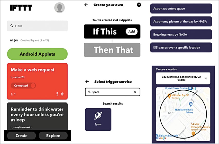
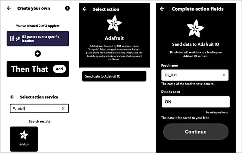
Now click on Then That block and search for Adafruit on the search bar. Click on ‘Send data to Adafruit IO’ (see Fig. 10), select the feed name (ISS_LED), and type ON in the ‘Data to save’ field.
After configuration of Adafruit and IFTTT has been done, all that is left is to upload the code. To recap, we have created a toggle switch on Adafruit that can control your NodeMCU via Wi-Fi. And we have created an applet on IFTTT that toggles the Adafruit switch every time the ISS passes over the selected location.
ISS Tracking Lamp Code
The heart of the ISS globe is the NodeMCU, which needs to be coded to work the way we want it to. Make sure you have the NodeMCU and Adafruit mqtt libraries installed on your Arduino IDE. The source code ISS_LED_SAMPLE.ino shown in Fig. 11 needs to be changed a bit for it to work.
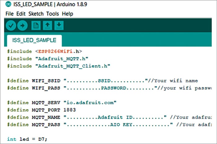
Make the following changes in the sample code:
- Replace SSID with your Wi-Fi (or mobile hotspot) name.
- Replace PASSWORD with your Wi-Fi (or mobile hotspot) password.
- Replace Adafruit ID with your Adafruit username.
- Replace AIO KEY with the active key you had noted after creating the Adafruit toggle switch.
If you named your Adafruit feed as ISS_LED you are done with editing of the code. But if you have used a different name, replace ISS_LED everywhere in the code with the name you have used.
This code keeps the LED turned off by default. When the ISS arrives, the LED starts blinking. In case you want the LED to remain on by default, you can replace digitalWrite(led,LOW); with digitalWrite(led,HIGH); in the first line of the void loop() function.
Now you can go ahead and upload the code to your NodeMCU. Please note, during testing, EFY Lab USERNAME was efytech2 and #define IO_KEY was aio_sXlY05Iri6o3ueuWYLLY5KnZIcAa, which were included in the source code ISS_LED_SAMPLE.ino before uploading. For the location of the ISS, the website https://www.astroviewer.net/iss/en/ was used.
Circuit Diagram
In this last step of getting the project working, connect the LED to the D7 pin of your NodeMCU. The 330-ohm resistor in series (as shown in Fig. 12) is used to limit the current through the LED.

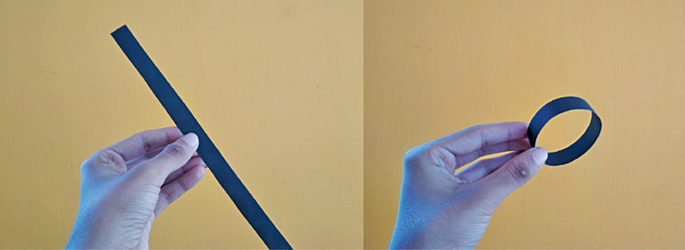
To make the base of the ISS lamp, you may cut a strip of black cardboard and roll it into a cylinder. The height of the cylinder (width of the strip) should be a bit more than the height of the NodeMCU when it is resting on its pins. The dia of the cylinder should be the same as that of diffuser’s base.
Cut another piece of cardboard in a circular shape with a diameter equal to the diameter of the cardboard cylinder and stick the cylinder to it with adhesive. Place the NodeMCU and the LED inside this cardboard base and place the diffuser on top (refer to Fig. 13 through Fig. 15).
Your very own ISS overhead indicator is now ready. Every time the ISS passes over your location, the lamp will let you know.
The ISS crosses a location once or twice most days (sometimes in the dead of night when it may not get noticed). There are some days when it does not show up at all, but that’s rare.
It feels good to know there are people working up there in ISS and it is exciting when they are just overhead. When ISS arrives after sunset, you can even run out and have a look at it moving in the sky and maybe wave a hello!
Download Source Code
Arpan Mondal is pursuing aerospace engineering and is an innovative project creator. He also likes playing guitar and sketching
