


Installation
The setup file 5SpiceAnalysis210.exe is 6.95MB. Double click on the file and the installation wizard assists you to get the program installed. The WinSpice included with the package is self-installing.
The main goal of the program is the design and analysis of analogue circuits at the component level.
Working with 5Spice
The main window of 5SpiceAnalysis2.10 is shown in Fig. 1. Here you can start designing the circuits. A title block can be found on the bottom right of the main window. Double click on it (or right click on it and select Edit Parameters) in order to add or edit the details of the file. The toolbar on the right side of the main window allows you to select from amongst a large number of predefined components like transmission lines, wires, resistors, capacitors, inductors, semiconductor devices (diode, BJT, JFET and MOSFET), transistors, op-amps, voltage and current source, test points, ground, transformers, etc. You can even add readymade logic gates, comparators, latches, flip-flops, counters and even include user-defined parameters. But the option to save digital logic circuits is available only in registered version of the software.
Click on the desired components and click where on the drawing board you would like to include them. You can add multiple copies of the same component this way. You can deselect the component by right clicking anywhere on the workspace, and perform necessary editing to the added component or include a new type of component in the design. Right click on the component to move them, edit the parameters and rotate or flip as required. You can add text notes relating to each circuit by clicking on the NOTES tab. These are saved along with the file. Once the circuit is completely built, the analysis can be performed.
 As mentioned in the features, this software has a wizard that allows the user to check whether the design entered matches the default designs given in the library of this program. This option comes in the menu bar under Analyse > Project Defaults Wizard.
If you are not ready to create your own circuit, a set of demo files are already included in the library of the program, to assist the users. These can be opened by going to File > Open Demo and selecting the required file. Fig. 2 shows such a loaded demo schematic of astable circuit, the transient analysis graph of it being shown in Fig. 3.
To perform the analysis, go to the menu bar Analyse > Run, or press F9. This simulates the working of the circuit, generates an analysis under a new tab, and produces a report of values and frequencies under REPORTS tab.
Click on the Lock button in the graph tab to prevent it from being overwritten by the next analysis. A multi-page schematic can be created in registered version.
The menu bar has a drop-down menu avoiding errors that cover almost all error possibilities.
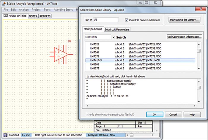
One can also specify the model of a component so that 5Spice can simulate it properly. As an example, let us select an op-amp LM741. Right click on it and select Edit Parameters from the drop-down menu. In the window that appears, the user can select LM741 from the given models of op-amps, as shown in Fig. 4. Then the manufacturer-specified parameters are loaded to the given op-amp. You can easily add other manufacturers’ SPICE models to the library as 5Spice is compatible with most of them.
5Spice is a quick-and-easy tool for analogue circuit design and simulation at component level. The main window is like a breadboard and the analysed graph acts as your oscilloscope screen, hence this is a very good way to test your circuits before building them on a breadboard. The complex analysis capabilities and simple user interface make it suitable for circuit designers at all levels—be it professionals or students. These qualities make 5Spice one of the best free tools available for circuit analysis.
Download latest version of the software: click here
The author is a technical correspondent at EFY Bengaluru