


Metal oxide semiconducting field effect transistor, commonly known as MOSFET, is a voltage-controlled device that is normally used as a switch or amplifier. It is considered one of the most crucial electronic devices in bringing about the modern electronics revolution. This semiconducting switch finds application in a wide variety of operations, especially where power conversion takes place. However, a power MOSFET remains one of the most common causes of failure of high-power circuits like converters and inverters. Failure of a power MOSFET can be due to various reasons, but the most frequent is selection of a wrong power MOSFET for the application. This article covers the different types of MOSFETs and factors to consider while selecting a power MOSFET.
MOSFET is a voltage-controlled 3-terminal device with source, drain, and gate as the three terminals. The basic idea of the 3-terminal device is to control the flow of current through one of its terminals by accurately controlling the voltage between the other two terminals.

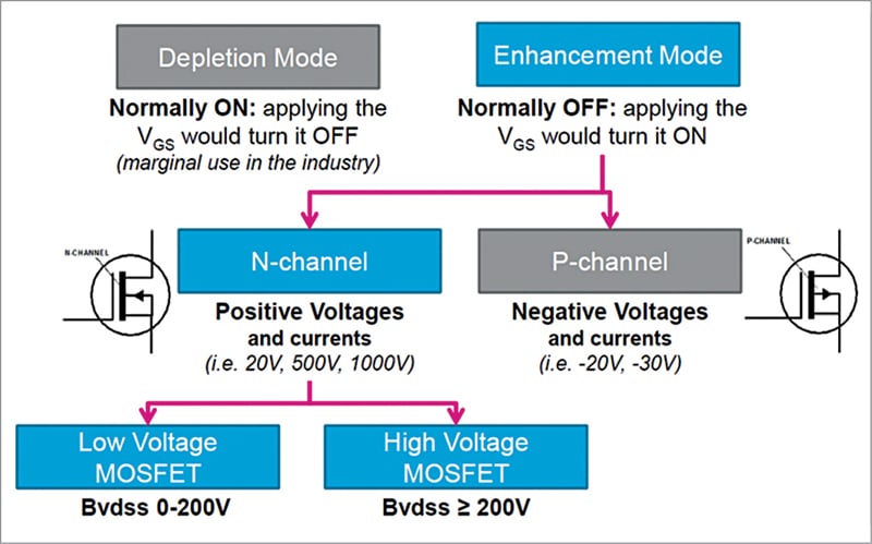
MOSFETs can be categorised based on the type of doping, whether N-channel or P-channel. Both types can further be classified on the basis of operation, that is, whether it is an enhancement type MOSFET (E-MOSFET) or depletion type MOSFET. Thus, there are following four types of MOSFETs:
- N-channel enhancement mode MOSFET
- P-channel enhancement mode MOSFET
- N-channel depletion mode MOSFET
- P-channel depletion mode MOSFET
Depletion mode MOSFETs are normally on, and applying VGS voltage turns them off. Enhancement mode MOSFETs are normally off, and applying VGS voltage turns them on. The flow chart in Fig. 2 shows how different types of MOSFETs work.
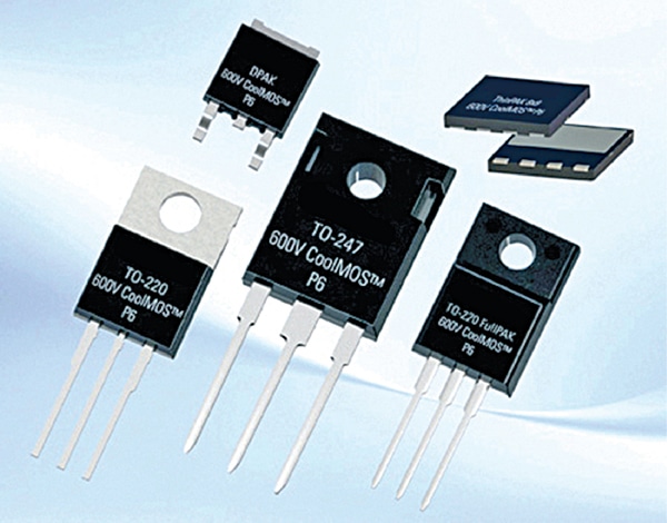
Power MOSFET is the most used power semiconductor device in the world. It is an enhanced version of a regular MOSFET that is capable of handling significantly higher power levels compared to any other semiconductor device, such as an insulated-gate bipolar transistor (IGBT) and a thyristor.
A power MOSFET has significant advantages, which include high low-voltage efficiency and a high switching speed. It also has a good paralleling capability, that is, multiple MOSFETs of similar type can be connected parallelly to allow a much higher amount of current to flow through the setup.
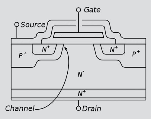
Double-diffused MOSFET, commonly known as DMOS, is one of the most commonly used power MOSFETs. It is commonly used in high-voltage, high-frequency switching applications. The double diffusion process is used to form the source and a channel region of this MOSFET. Fig. 3 shows the cross-section of a power MOSFET.
Important MOSFET parameters
Two important parameters of a MOSFET that are crucial while selecting a MOSFET are the on-resistance, Rds(on), and the gate charge, Qg. These two parameters are interrelated and are responsible for the efficiency of the system.
Some other important parameters that determine the performance of a MOSFET are the breakdown voltage, BVDSS, and the body drain diode, which is essential to take into account when the device is used as a power diode, like in synchronous free-wheeling operation mode, and intrinsic capacitances that can affect the switching times and voltage spikes.
On-state resistance, RDS(on)
It denotes the resistance between the drain and source terminals when the MOSFET is in on state. The conduction loss depends on it; the lower the value of the RDS(on), lower is the conduction loss.
Total gate charge, QG
It denotes the electric charge required by the gate driver to turn the device on/off.
Figure of Merit, FoM
It is the product of RDS(on) and QG, which accounts for the conduction losses and switching losses of a MOSFET. Therefore, the efficiency of a MOSFET depends on both, the RDS(on) and the QG.
Breakdown voltage, BVDSS
It denotes the maximum drain-to-source voltage a MOSFET is capable of sustaining in off state.
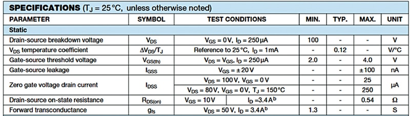
An example of a MOSFET’s datasheet parameters is given in Fig. 4.
| Steps to select a power MOSFET |
|
1. Find out all the parameters of application, such as maximum voltage, maximum current, and operating temperature.
2. Find out the total load of the circuit. 3. Calculate peak current and peak load required for the MOSFET. 4. Find out the efficiency of the system. 5. Now calculate the load with losses. 6. Add a safety factor (depending on the temperature of operation). 7. Check if the device will operate as a bi-directional device or not. |
Selecting a power MOSFET
Selecting the right power MOSFET with correct characteristics and appropriate ratings is important for designing a great circuit. The device should have operating conditions or working range that tells us the safe conditions for its working. The absolute maximum ratings are the limiting values, exceeding which might cause permanent damage or failure of the circuit.
“Selection of a MOSFET is very crucial for the stability of a system,” says Mrinjal Upadhayay, R&D engineer at Statcon Energia. He continues, “While selecting a MOSFET for any operation we always consider the peak current and voltage and not the operational current.”
The drain-to-source voltage ratings (VDS) should be at least 20% higher than the supply voltage, while the motor load should be higher than the peak load condition. For some cases with high currents, large torque steps, poorly controlled power supplies, etc, a higher margin is required.
The MOSFET should be rated at least for the maximum voltage and the maximum current for the power required. For the motor applications, its current rating should be higher than the peak current. Besides, thermal consideration also plays a vital role in the selection of a MOSFET.
The MOSFETs generate heat due to the drain-source resistance. Thermal constraints tell us about the maximum power that can be dissipated, and the maximum allowable power dissipation drives the selection of the MOSFETs based on the RDS(ON) value.
After determining the necessary voltage rating and RDS(ON), the gate charge (QG) value is considered. It determines the speed of the switching and efficiency of the MOSFET. It will switch faster with a device having lower gate drive current than one with a high QG.
An example for selection
As an example, let us see how to select a MOSFET for a 12V inverter for a residential application. Let us say the parameters known to us are:
Input – 12V DC (lead-acid battery)
Output – 230V AC
Load – 1000W
Peak load – 2000W
Losses in inverter – 20%
Step 1. Consider the maximum power output at peak load. (While calculating we only consider the maximum output power.)
P_max=2000W
Total loss is 20% of 2000W, so the total loss is 400W
Step 2. Find out the total load
Total load=Maximum load+ Load due to losses
=2000W+400W
=2400W
Step 3. Calculate peak current and peak load
The input side of the inverter has a lead-acid battery, which will usually have a charge anywhere between 10V and 14V. Therefore, keeping 20% to 40% margin, the input will be approximately 6V to 8V.
Current=P/V=2400/6=400A
Step 4. Calculating the voltage
A minimum of 2x voltage is selected to keep the system stable, because during a short-circuit or peak current a voltage spike is also observed. It is safer to select a higher voltage.
Maximum battery voltage (V_Bmax)=14V
MOSFET rating=2×14V=28V
Step 5. Adding safety factor to the current
The safe operation area of MOSFET is temperature dependent. So, in order to make the system more secure, we may take 50% to 80% higher current rating than the calculated current.
Let us take a safety factor of 50%.
I_S.F.=400A+200A=600A
So, the MOSFET we require should be rated for 600A. Therefore, the suitable MOSFET for our operation should be rated for at least 600A and 28V.
SiC vs GaN vs Si MOSFET
For higher powered applications, the silicon carbide (SiC) and gallium nitride (GaN) MOSFETs are replacing the silicon MOSFET. Both SiC and GaN MOSFETs are capable of sustaining higher frequencies and higher voltages compared to the silicon MOSFETs. Higher switching frequency corresponds to lower passive components.
Both SiC and GaN MOSFETs have higher bandgap compared to their silicon counterparts. Furthermore, SiC and GaN MOSFETs have better thermal conductivity and higher electron conductivity, which makes them more suitable for higher power operations. Compared to the silicon MOSFET, the other two devices eliminate tail current during switching, thus reducing switching loss and providing a faster operation.
The table on previous page compares the Si, GaN, and SiC MOSFETs.
In power electronics systems, where a motor needs to be driven, employing a pre-driver or a gate driver circuit is essential for improving the efficiency and stability of the system. The gate driver circuit is mostly used with an N-channel power MOSFET in order to deliver high current to the motor. The design of gate driver circuit and selection of driver IC depends on the parameters of motor.
MOSFETs are the main building blocks of power electronics circuits. Power MOSFETs can be found in high-power applications, such as:
- Switch mode power supplies (SMPS)
- Automotive applications
- Residential, commercial, architectural, and street lighting
- DC-DC converters
- Motor control
The author Sharad Bhowmick works as a Technology Advisor at EFY. He is passionate about power electronics and energy storage technologies. Through his work, he wants to help achieve the goal of a carbon-neutral world