With so many kinds of motors available in the market, often it becomes difficult to select the most appropriate for an application. So, in such situations, the designers go for anything that comes to their mind as a suitable motor—without looking at the other options that could be better. Here is an introduction to all the motors that are available to choose from, and depending on the application designers can now select the most suitable one for an application.
Here are some guidelines for selecting the best motor for an application, among the many available in the market, such as the universal motor (UM), AC induction motor (IM), permanent magnet motor (PMM), permanent magnet synchronous motor (PMSM), synchronous reluctance motor (SynRM), switched reluctance motor (SRM), and the latest assistive permanent magnet synchronous reluctance motor (IPM-SynRM) offered by Tesla Motors.

Engineers have many options to choose from for their projects. Picking the wrong motor can condemn the design to normality and market failure.
Universal motors
The universal motor (UM) is a type of electric motor that can run on AC or DC power and uses an electromagnet as a stator to create its magnetic field. It is a switched series-wound motor where the stator field coils are connected in series with the rotor windings through a commutator. It is often referred to as the AC series engine.
The universal motor is very similar to a DC series motor in construction but is slightly modified to allow the motor to operate correctly on AC power. This type of electric motor can operate well on AC because the current in the field coils and armature (and the resulting magnetic fields) will alternate (reverse polarity) in sync with the supply.
Consequently, the resulting mechanical force will occur in a consistent direction of rotation, independent of the direction of the applied voltage, but determined by the commutator and polarity of the field coils.
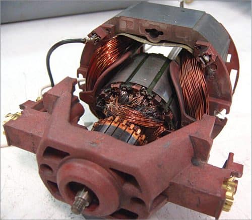
Universal motors have high starting torque, can run at high speed, and are light and compact. These are commonly used in portable electrical tools and equipment, as well as in many household appliances. The motors are relatively easy to control, electromechanically using derived coils or electronically. However, the commutator has brushes that wear out, so these are much less used for equipment that is in continuous use. Also, in part because of the commutator, universal motors are often very noisy, both acoustically and electromagnetically.
Not all series-wound motors work well on AC current. If a DC motor with a common series coil were connected to an AC source, it would malfunction. The universal motor is modified in several ways to allow for proper operation of AC power. There is a normally added compensating winding, along with the laminated pole pieces, as opposed to the solid pole pieces found in DC motors. The armature of a universal motor typically has many more coils and plates than a DC motor and therefore fewer windings per coil. This reduces the inductance.
Even when used with AC power, these motors can run at a rotational frequency well above the mains supply and, as most electric motor properties improve with speed, this means they can be light and powerful. However, universal motors are generally relatively inefficient by around 30% for smaller ones and up to 70-75% for larger ones.
Their advantages:
- Universal motors are cheaper due to their simple construction and do not require permanent magnets.
- Universal motors provide good torque at low speeds.
- These can rotate at high speed due to the connection of armature windings and field windings in series.
- Due to their small size and light weight, universal motors are preferred in many applications.
- Eddy current losses are reduced due to the presence of an electromagnetic field and heating is avoided.
- Universal motors require low power input to operate the motor.
- The engines can run at any given speed.
Their disadvantages:
- Universal motors produce relatively loud noise, which increases with motor speed.
- There are high chances of vibrations, which can damage the engine.
- There is no possibility of turning the motor in the opposite direction.
- These engines cause overheating.
- Universal motors require frequent maintenance due to rapid wear and tear of brushes and commutators.
Their applications:
- Domestic appliances like vacuum cleaners and sewing machines
- Blenders, portable drills, etc
- Polishers and other machines
- Electric shavers
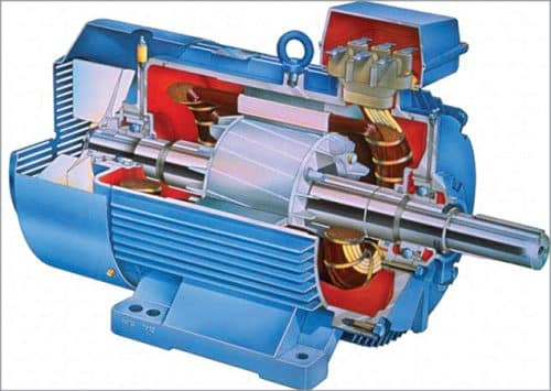
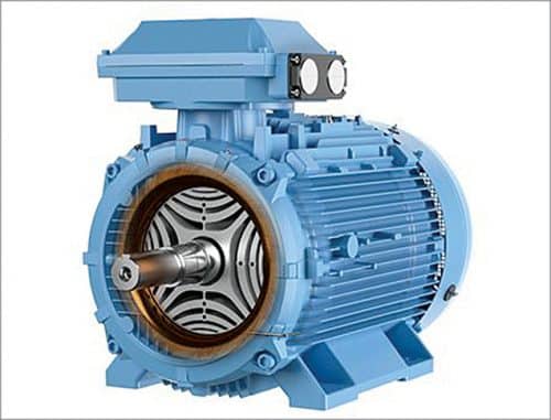
AC induction motors
AC induction motors are primarily the workhorse of the industry and for good reasons. These combine performance with simplicity. The motors can be controlled directly from AC sources, which was an important function in the past. Today, thanks to digital signal processing and advanced power electronics, it is relatively inexpensive to change the speed of instant messaging.
Modern control algorithms allow induction motors to serve where expensive brush motors were previously used. The resulting energy savings directly lead to increasingly significant financial and environmental benefits. That is why controlled induction motors can be easily found in a variety of cost-critical applications such as washing machines and electric vehicles, as well as in the industrial world of blowers, pumps, fans, and material handling.
An induction motor generates torque by the interaction of its rotating stator field with induced currents in the rotor conductors. However, conductors heat the rotor, which reduces the efficiency and life of the bearings. Replacing traditional aluminium rotor conductors with copper versions helps a little, but they are expensive and can prohibit direct starting.
Their stator’s electrical time constant is long; therefore, to ensure an acceptably fast response to changes in load or speed, it is common to operate the motor at a constant magnetic flux up to ‘base’ speed. Unfortunately, associated magnetisation losses are then present, no matter how hard the motor is running, resulting in low light-load efficiency.
Automatic stator flux reduction at low torques is possible, but only if fast control responses are not required. At speeds above base speed, the stator field weakens due to the limited supply voltage, so controlled induction motors generally provide constant mechanical energy. Efficiency drops quickly, however, because stray inductance causes the rotor current to fall behind the rotating field, so more rotor current is needed for a given torque.
Consequently, controlled induction motors are limited to a constant power speed range (CPSR) of about 2:1. Applications that require a wider CPSR, such as vehicle traction and machine tools, can be achieved by decreasing the number of winding curves and discarding excess torque capacity at lower speeds. Higher stator currents make drives more expensive and less efficient.
Please note, induction motors’ nameplate efficiencies are quoted for pure sine wave operation. In real-world scenarios, inverters deliver pulses that only approximate sinusoidal current. Design teams should note that the overall system efficiency (motor and drive) will be less than the product of the individually quoted values for the motor and drive. Higher carrier frequencies help but increasing motor power results in higher drive losses.
A solution lies in placing filters between the inverter and the motor, but it introduces additional energy losses and is expensive. Also, the filters are quite big. Another disadvantage of AC induction motors is that the stator windings are distributed over many grooves in the stator core. That means long end curves that waste space and energy.
Their advantages:
- Induction motors do not require brushes, slip rings, and commutator arrangements. That means they are very simple to build.
- As there is no brush and slip ring arrangement, the mechanical or friction loss is very low, therefore, the efficiency of the induction motor is very high. The efficiency of an induction motor can be expected to be between 85-95%.
- No special arrangement is needed for the winding to create north poles and south poles like a DC motor. It automatically poles with the polarity of AC power.
- As induction motor does not have brushes, slip rings, commutator, it is a very low-cost machine compared to a DC motor or other motors.
- Although a single-phase induction motor requires a starting arrangement such as a capacitor, three-phase induction motors are auto-starting.
- Induction motors are of very simple construction, so their maintenance is much less compared to other motors.
- As an induction motor operates on AC power, there is a very low loss of I2R compared to DC motors.
- The induction motor provides very good speed range and can be operated in any environmental condition; even at 400°C.
- The starting method of induction motors is very simple. This means that induction motor starters are much simpler than DC motor starters.
- The induction motor creates very low noise, vibration, etc.
Their disadvantages:
- Throughout the light-load situation, the power factor is extremely less, and it draws a huge current. So, the copper loss can be high, which decreases the efficiency throughout the light load situation.
- The squirrel cage induction motor’s initial torque is not low.
- This is an invariable-speed motor, so cannot be used where variable speed is required.
- This motor’s speed control is not easy.
- The motor includes a high starting inrush current, which causes a reduction in voltage at start time.
Their applications:
- Lifts
- Cranes
- Hoists
- Large-capacity exhaust fans
- Driving lathe machines
- Crushers
- Oil extracting mills
- Textile industry, etc
Permanent magnet motors
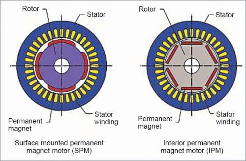
Permanent magnet motors generate torque by interacting stator currents with permanent magnets on or inside the rotor. Surface rotor magnets are common in small- and low-power motors for commercial machines, IT equipment, and automotive auxiliaries. Internal magnets are trivial on larger machines like electric vehicles and in industrial motors.
In permanent magnet motors, stator can use concentrated (short-pitch) windings if or when torque ripple is not a problem, but distributed windings are the criteria in larger motors. Since these motors do not have mechanical switches, inverters are essential to control their winding current.
Unlike other types of brushless motors, permanent magnet motors do not require current to sustain their magnetic fields. Therefore, the motors provide maximum torque per volume and may be the best choice if light weight or small size is important. The absence of magnetising current also means greater efficiency in the ‘sweet spot’ load, that is, where the motors perform the best.
The most visible disadvantage of PMM is their high cost. High-performance permanent magnet motors use magnets made from transition metals such as dysprosium and neodymium. These materials are rare and come from geopolitically unstable countries, resulting in high and volatile prices.
In addition, while permanent magnets provide performance gains at lower speeds, they are also a kind of technical Achilles’ heel. For example, as the speed of a motor increases, its rear EMF approaches the inverter supply voltage, making it impossible to control the winding current. This defines the basic speed of a generic permanent magnet motor, and in surface magnet designs it generally represents the maximum possible speed for a given supply voltage.
At speeds higher than the base speed, the motors utilise weakening of the active field in which the stator current is varied to deliberately depress the flow of the magnet. The speed range in which this can be successfully done is limited to about 4:1. As before, this limitation can be circumvented by reducing the winding curves and accepting higher costs and energy losses in the inverter.
The requirement to weaken the field is related to speed and the associated losses arise heedless of the torque. This lowers efficiency at high speeds, notably for light loads. This happens in electric vehicles, where cruising at highway speeds inevitably involves weakening the field. Permanent magnet motors are often favoured for EVs, but the efficiency gain is questionable when computed in real-world driving cycles. In an interesting observation, at least one major EV manufacturer has switched from permanent-magnet to induction motors.
Another disadvantage of the motors lies in the fact that they are infamously challenging to handle in failure conditions due to their built-in rear EMF. Current continues to flow in winding faults as the motor spins, even if the inverter is not connected, causing overheating and cogging torque, both of which can be dangerous. The loss or weakening of the field at high speeds, for example due to shutdown of the inverter, leads to uncontrolled generation and the voltage of the inverter DC bus can increase to dangerous levels.
One more significant limitation is the operating temperatures for all permanent magnet motors, except those equipped with samarium-cobalt magnets. And high motor currents, which can arise due to inverter failures, can force demagnetisation.
The maximum speed for the motors is defined by the mechanical retention of the magnet. If a motor is damaged, repairing it normally involves sending it back to the factory due to the difficulty of safely pulling out and handling the rotor.
Finally, recycling at the end of its useful life is also problematic, although the high current value of rare earth materials can make this more economically viable.
Despite these flaws, these motors remain unrivalled in terms of low speed and sweet spot efficiency and are useful when weight and size are critical.
Permanent magnet synchronous motors
The main difference between a permanent magnet synchronous motor and an induction motor lies in their rotors. Studies show that a synchronous motor has an efficiency of approximately 2% more than a highly efficient (IE3) induction electric motor, provided their stator has the same design and the same variable frequency drive is used for control. In this case, permanent magnet synchronous electric motors in comparison with other electric motors have the best performance: power/volume, torque/inertia, etc.
A permanent magnet synchronous motor, like any rotating electric motor, consists of a rotor and a stator. The permanent magnet synchronous motor is efficient, brushless, fast, safe, and give high dynamic performance as compared to the conventional motors. It produces smooth torque, low noise and is mainly used for high-speed applications like robotics. It is a 3-phase AC synchronous motor that runs at synchronous speed with the applied AC source.
Instead of using winding for the rotor, permanent magnets are mounted to create a rotating magnetic field. As there is no supply of DC source, this type of motor is very simple and costs less. It contains a stator with three windings installed on it and a rotor with a permanent magnet mounted to create field poles. The 3-phase input AC supply is given to the stator to start working.
The permanent magnet synchronous motor working principle is similar to the synchronous motor. It depends on the rotating magnetic field that generates electromotive force at synchronous speed. When the stator winding is energised by giving 3-phase supply, a rotating magnetic field is created in between the air gaps. This produces the torque when the rotor field poles hold the rotating magnetic field at synchronous speed and the rotor rotates continuously.
As these are not self-starting motors, it is necessary to provide a variable frequency power supply.
Their advantages:
- Provide higher efficiency at high speeds
- Available in small sizes and different packages
- Maintenance and installation is much easier than an induction motor
- Capable of maintaining full torque at low speeds
- High efficiency and reliability
- Give smooth torque and dynamic performance
Their disadvantages:
• Very expensive as compared to induction motors
• Somehow difficult to start as these are not self-starting motors
Their applications:
- Air-conditioners and their compressors
- Refrigerators
- Washing machines, which are direct-drive
- Automotive electrical power steering
- Machine tools
- Large power systems to improve leading and lagging power factor
- Control of traction
- Data storage units
- Servo drives
- Industrial applications like robotics, aerospace, and more
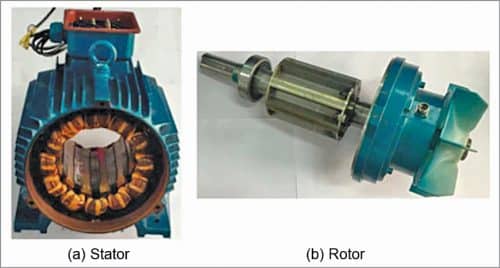
Synchronous reluctance motors
Modern synchronous reluctance motors are always inverter powered and use the same type of distributed wound stators as the AC induction motors. However, their rotors are made of laminated steel with punched slots, so these can be easily magnetised in one axis and less so in the other. The tendency of these rotors to cope with the rotating field of the stator creates torque. Like the permanent magnet motors, these are self-synchronous, which means that the inverter synchronises the stator supply to the rotor angle and speed.
The main advantage of synchronous reluctance motors is their negligible rotor losses compared to induction motors. So, with thorough design and control, the motors will be able to meet motor efficiency guidelines in future European IE4 and NEMA standards without the need for magnets. The reduced heat in synchronous reluctance motors improves torque and power densities compared to industrial motors and allows them to be usually one dimension smaller for a given rating. These motors are also quite due to low torque ripple and vibration levels.
A somewhat discussed disadvantage of synchronous reluctance motors is their low power factor compared to industrial motors. So, a significantly higher inverter current is required for a given level of mechanical power, which increases the cost and power loss of the inverter. It means, while the efficiency of synchronous reluctance motors can be good, their system-level benefits are less convincing.
Standards currently address efficiency with motors only, and designers should carefully examine the likely overall performance of the system. The need for complex laminations of rotors with their punctured flow barriers makes synchronous reluctance motor rotors difficult to manufacture, somewhat brittle, and therefore not suitable for high-speed operations.
Synchronous reluctance motors are suitable for a wide range of industrial applications that do not require high overloads and high speeds. These are also increasingly being offered for variable speed pumps due to their efficiency.
Their advantages:
- There is no concern of demagnetisation, so these are inherently more reliable than permanent magnet motors
- There need not be any exciting field as torque is zero, thus eliminating electromagnetic spinning losses
- Synchronous reluctance machine rotors can be constructed entirely from high-strength, low-cost materials
Their disadvantages:
- High cost compared to induction motors
- Need speed synchronisation to inverter output frequency by using rotor position sensor and sensorless control
- Compared to an induction motor it is slightly heavier and has low power factor. But by increasing the saliency ratio Lds/Lqs, the power factor can be improved
Their applications:
- Metering pumps
- Auxiliary time mechanism
- Wrapping and folding machines
- Proportioning devices on pumps or conveyors
- Synthetic fibre manufacturing equipment
- Processing continuous sheet or film material
Switched reluctance motors
Switched reluctance motors generate torque by magnetically pulling the rotor protrusion to the stator field. However, their stators have relatively few poles. Their rotors are also much simpler with magnetic protrusion due to the toothed profile rather than due to the internal flow barriers in synchronous reluctance motors. The difference in the number of stators and rotor poles causes the Vernier effect and the switched reluctance motors rotor usually rotates in the opposite direction and at a different speed than the stator field.
Unlike synchronous reluctance motors, switched reluctance motors typically use DC pulse excitation and require special inverters to operate. A certain current is required to support their magnetic field, leading to lower torque density and efficiency at sweet spots than permanent magnet motors. However, like synchronous reluctance motors, switched reluctance motors are usually one frame size smaller than comparable induction motors.
The great advantage of switched reluctance motors is that field weakening occurs naturally when excitation decreases, without loss of efficiency. As a result, a wide CPSR (greater than 10:1) is easily possible. Efficiency remains good at higher speeds and low loads, and the motors can achieve remarkably constant efficiencies over a wide range of operating conditions.
Switched reluctance motors are also extremely fault tolerant. Without magnets, there is no uncontrolled torque, current under faulty winding conditions, or uncontrolled generation at high speeds. Further, as the switched reluctance motor phases are electrically independent, the motor can, when or if desired, run at reduced power but with higher torque ripple when one or more phases are off. This can be useful if designers want fault tolerance and redundancy.
Thanks to the simple construction of switched reluctance motors, they are durable and undemanding to production. No expensive materials are required and the plain steel rotor is suitable for high speeds and harsh environments. And short-pitch stator coils reduce the risk of short-circuit windings. In addition, the end speed can be short, so the switched reluctance motors are efficiently small and prevent unnecessary stator losses.
The power factor of the switched reluctance motors is lower than the power factor of permanent magnet or induction motors, but the inverter does not need to synthesize a sine wave for efficient motor operation. The switching frequencies of the inverter and the associated switching losses are therefore low.
The main disadvantages of switched reluctance motors are acoustic noise and vibration. These can be controlled by careful mechanical construction, electronic control, and motor design of the application.
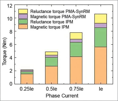
Surface rotor magnets (SPM) and internal magnet motors (IPM) are both variants of permanent magnet motors. AC, SPM, and IPM motors show low performance in high-peed range (field attenuation). Stable induction motor capacity is weak unless the motor is powered by an inverter.
Switched reluctance motors are suitable for a wide range of applications and are increasingly used in the handling of heavy materials due to their large moments of rupture and overload. Thanks to their high switched reluctance motor overload capability and wide range of constant power, they are attractive for vehicle traction, not only in off-road equipment but also in cars where they still have to assert themselves. This may be due to concerns about acoustic noise or torque ripple, but it should be borne in mind that an internal combustion motor is successful despite being an excellent source. The use of a switched reluctance motor with a permanent magnet increases the efficiency by several percent compared to an induction motor.
Their advantages:
- Low cost resulting from simple construction
- High reliability
- High fault tolerance
- Heat generated in stator is easy to remove
- High-speed operation possible
Their disadvantages:
- Acoustically noisy
- High vibration
- Magnetic non-linearities make smooth torque control difficult
- Dependent on electronic control for operation
Their applications:
- Domestic appliances such as washing machines, vacuum cleaners, and fans
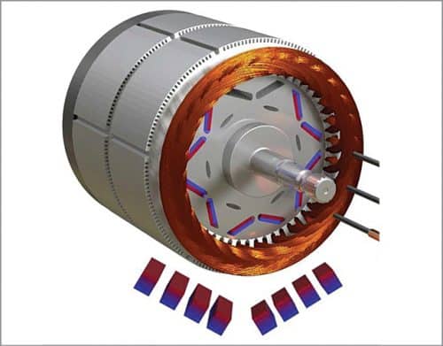
IPM-SynRM electric motors
The Tesla internal permanent magnet synchronous reluctance motors (IPM-SynRM) are now used in some Tesla electric vehicles. Earlier, Tesla Motors used induction (or asynchronous) electric motors. From Model 3 onwards, the company has been using the IPM-SynRM motors, also known as a PMa-SynRM (permanent magnet assisted synchronous reluctance motors).
In general, it is a type that joins a motor type with an internal permanent magnet and a rotor type with a synchronous reluctance motor to fulfil the requirement characteristic in an electric vehicle (EV) application—high efficiency at high or low speeds. Tesla is not the first to utilise this design of motor, but its variant is thought of as one of the best simply due to the high efficiency and range of Tesla cars.
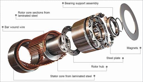
A specific innovation from Tesla is the use of segmented magnets of four parts instead of the more typical single fixed magnet inside the rotor of the motor. It helps reduce eddy currents and reduces the risk of magnets overheating.
Tesla Motor engineers made an impressive design choice when they developed the Tesla Model 3. They abandoned the conventionally used and proven induction motors and replaced them with a new type of motor, called the IPMSynRM motor. These motors have a totally different design, making use of magnetic action and reluctance. Tesla Motors began replacing the induction motors on their Model S and X with this new engine as well.
Each motor has a rotor and stator arrangement. In a simple induction motor, the rotating part of an engine is an arrangement of conducting bars. Since the stator creates a rotating magnetic field, the floating field interacts with the rotor bars and generates currents in the rotor bars. The induced currents and the RMF interact, imposing force on the rotor bars, and the rotor begins to rotate.
But there is a problem for long drives at cruising speed; losing 3% to 4% of the energy to generate currents in the rotor bars is definitely not efficient. That is why, to overcome this problem, Tesla replaced this engine in RWD and AWD cars with IPM-SynRM engine for better efficiency. The IPM-SynRM is a combination of permanent magnet and SynRM motors, which are integrated by placing the permanent magnets in the grooved cuts of the SynRM motor, deep in the iron core.
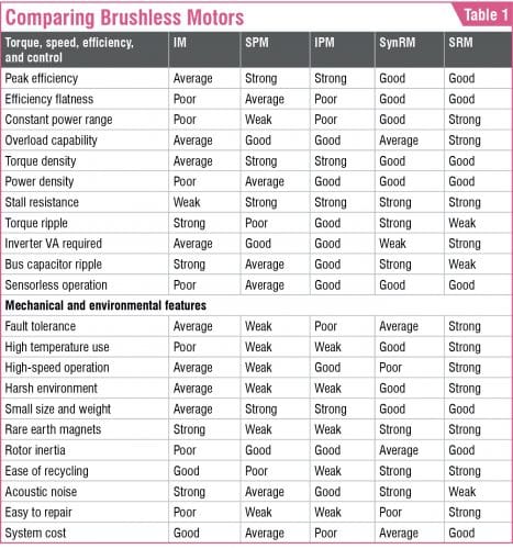
Please see Table 1 for overall comparison of different types of motors.
Jawaaz Ahmad from Srinagar is a Design Fellow at Design Innovation Centre, Islamic University of Science and Technology, Awantipora, J&K