


A dark, black screen. Symbols of a resistor, a capacitor and an inductor. A switch. Flashes of red, green and grey, and moving yellow dots. Graphs at the bottom of the screen, lines criss-crossing to create beautiful orderly curves on the screen. Click on the switch and the patterns change. The red disappears, the yellow moves differently and the grey is hardly there. Magically, a transition seems to have happened on the screen!
It does not take too much to figure out what is happening here. It certainly sounds like a circuit is kicking into action. An LCR circuit in fact. But is it possible to actually see what you can only begin to visualise? Certainly seems so! The above simply describes the window that greets you on venturing into the world of CircuitMod!

Does the scenario not sound exciting? Questions tumble into the mind one after the other. What is CircuitMod? Does it actually let you see action live? Can you make your own circuit? Does it actually mean you get to see what you have largely learnt only in theory?
Let us try to seek a few answers first.
What is the big deal anyway
First things first! CircuitMod is an electronic circuit simulator. But instead of simulating a schematic in the background and giving results to you, CircuitMod shows you what is happening in the circuit. Sounds confusing? Well, let us break it down. The schematic of the circuit appears on the screen like any usual circuit diagram. But start the circuit, and a mini movie begins.
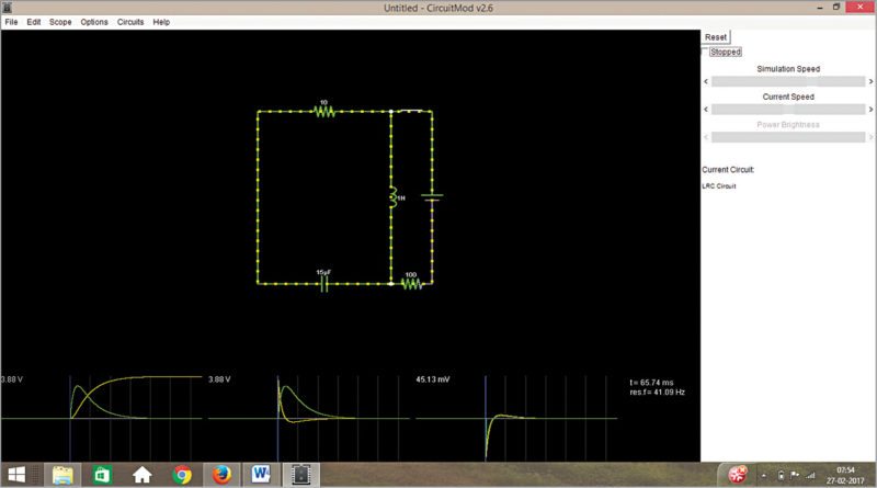
Every part of the circuit takes a colour depending upon the voltage in the area. Any wire with positive voltage is seen in green, grounded regions are grey and red indicates negative voltage. Current flows as yellow dots moving on the screen.
Three graphs at the bottom of the screen act like oscilloscopes to your design, each one showing the voltage and current across a particular component. Green traces being voltage and current traces being yellow, graphs are drawn as the circuit is simulated, and you can see the variation of current and voltage as the circuit simulates over time.
Observe, change, learn
This approach seems to have a lot of takers in newbies to the field or anyone who wishes to revisit the basics of electronics. CircuitMod seems to have been constructed with this approach in mind. Go into the circuit menu of the tool and you have a plethora of circuits to venture into. As you surf through the circuit list, each kicks into live action, demonstrating how the circuit functions for the given set of conditions.
Now, the obvious next question is whether you only get to learn from what is already there, and the answer to that is a firm no! The pre-included circuits form the basis of most circuits an electronics beginner deals with. From then on, you are at your free will. Modify the circuit as and how you want. It could simply be changing the values of the components involved, moving around two of these to create a small change, or adding new components to create a whole new version.
Options a click away.
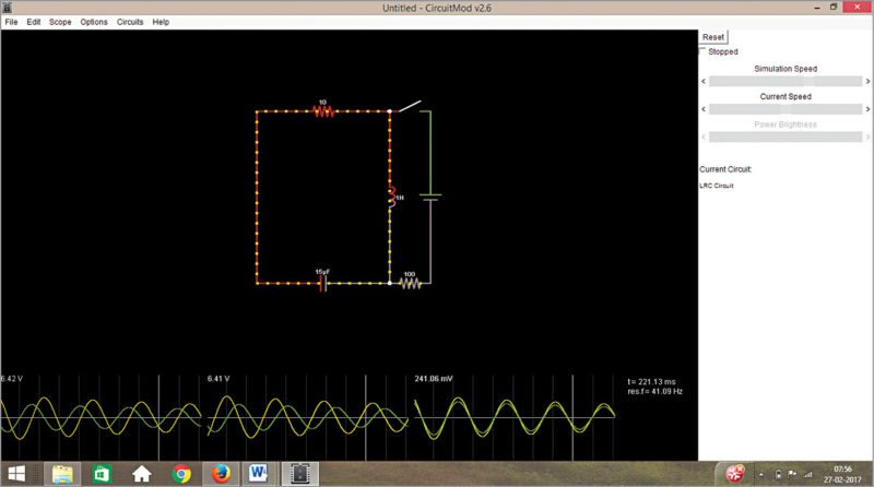
Turning the circuit on and off can be done by simply clicking on the switch. Move the mouse over the circuit, and as you pass each component, a short description of the component and its current state pop up at the lower-right corner of the screen. If you want to edit any part of the circuit, right-click on the corresponding component and you can see the edit window.
Graphs for better visibility.
Coming to Scope window at the bottom of the screen, you can see instantaneous voltage, current and power as these change with time, or you can stack these together and see a single window, and compare how the current and voltage trends vary.
As you move over the scope, the component it is graphing is highlighted in the circuit; you can change the scope data to show another component’s details. You can also adjust the speed of simulation according to the speed at which you want the circuit to function—a slow movie or an action flick, it is your choice!
Beginner’s luck
Let us take a look at some of the sample circuits already pre-loaded in CircuitMod. Here are a few categories of designs available:
Basics.
Resistors, capacitors, inductors. This is simply to appreciate the role of these components in any circuit. CircuitMod also includes voltage dividers for a set of voltage-generation, Thevenin’s and Norton’s theorems.
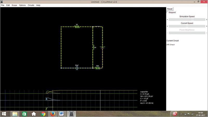
AC circuits.
Circuits depicting the behaviour of capacitors and inductors under an alternating current (AC) source and to different frequencies can easily be studied with the circuit spread under this section. Concepts of impedance, series resonance and parallel resonance are not difficult to grasp anymore.
Passive circuits.
Everything from filter and crossover circuits, to transformers and differentiators are illustrated here. There are also circuits that help you understand how exactly three- and four-way light switches work, why wheatstone bridge balancing is important to avoid current flow between its legs, and circuits performing inductive kickback action.
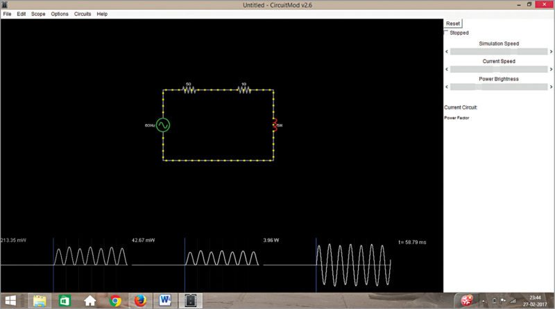
Power factor analysis.
Let us take an example to understand why this style of learning is so powerful. Consider an inductor being driven by AC voltage. Below is the explanation for the circuit as taken from Falstad website:
“The colours indicate power consumption; red means that a component is consuming power and green means that the component is contributing power. The left side of the circuit represents the power company’s side and the right side represents a factory (with a large induction motor). The highly-inductive load is causing the power company to work a lot harder than normal for a given amount of power delivered. The graph on the left indicates the power lost in the power company’s equipment (the resistor at top left). The graph in the middle is the power delivered to the factory. The graph on the right is the power delivered to the inductor (and then returned, causing the time average of power delivered to be zero). Even though a peak power of 40mW is being delivered to the factory, 200mW is being dissipated in the power company’s wires. This is why power companies charge extra for inductive loads.”
The above clarifies why thorough analysis of even simple circuits is very important and how exactly CircuitMod chips in here.
A little more.
Apart from the above, there are circuits involving diodes—be it rectifier or diode characteristics, voltage multipliers, communication-related circuits like detectors, transistors and op-amps in their various configurations, oscillators, JFETS, MOSFETs, timers, logic families, digital circuits, phase-locked loops and transmission lines; basically, the entire package.
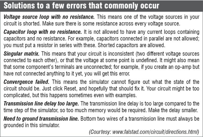
Tried and tested
The tool is at your disposal. How effective is your learning depends on how much you exploit the available resources. Play around with the options. You can not only modify the circuit, but also the way these look. Replace resistors with European-style ones, change the screen background to white, reverse conventional current direction—the options are quite a handful. Explore and enjoy!

i want this software please suggest me