


Computer-aided design (CAD) software basically makes use of a computer to assist in the creation, optimisation, analysis or modification of a design. From increasing the productivity level of the designer to improving the quality of designs to creating and maintaining a database for manufacturing, CAD software are used extensively across many verticals. Let’s discuss more about zamiaCAD.
Abhishek Mutha
zamiaCAD is a project which aims at transferring the advances in software development to the hardware development discipline. The zamiaCAD project targets to support state-of-the-art and future large-scale industrial hardware designs. This framework is developed to provide the research community with a robust open source research platform that is equipped with powerful debugging functionality.
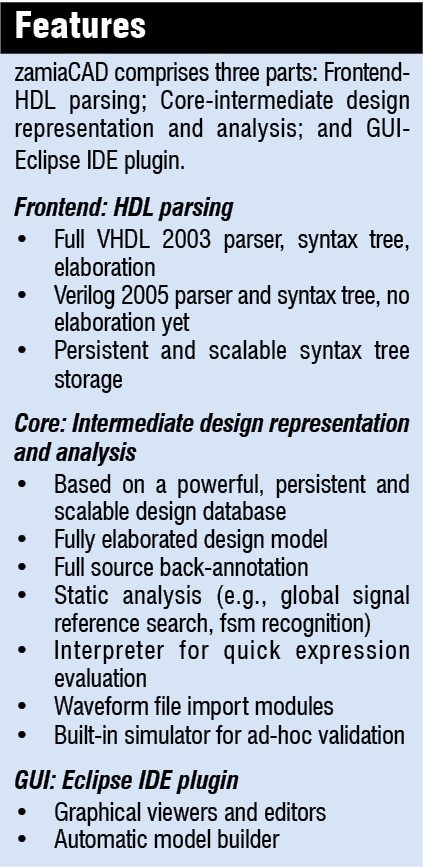
Written in Java, zamiaCAD is an extensible and modular platform for research, analysis and advanced hardware design. Its core components are language-dependent frontends generating an instantiation graph (IG), applications working on the IG data structure and the language-independent IG data structure. The frontends consist of an elaboration engine and a parser. Currently, Verilog has only a parser, whereas VHDL has a complete frontend. There are also a number of video tutorials available on the website to give the users an idea of how zamiaCAD looks and feels like.

Basic build process
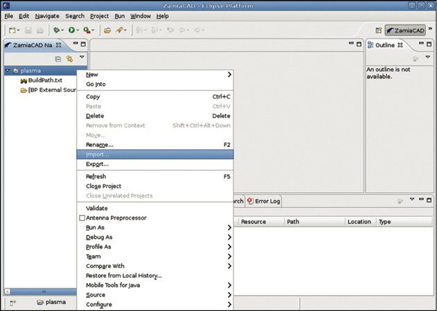
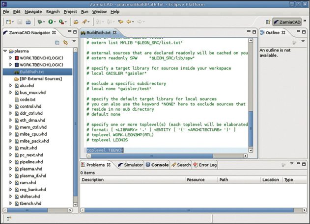
zamiaCAD has a complete VHDL compiler with project build facilities. The entire build process is actuated by the BuildPath.txt file, which informs the builder about the location where he/she can find the sources and libraries to put them into. Since sources may be stored on high-latency network mount points (for example NFS or AFS mounts), zamiaCAD has a built-in file system cache (FSCache), which it uses to cache files and directory information on the user’s local disk for speed.

Parsing all VHDL sources that are accessible through the directories configured in a project’s BuildPath.txt can be very time consuming. Since a significant portion of the design units defined in those files might never actually get instantiated or used in the project (this is especially true for technology/simulation libraries), it is often not necessary. Therefore zamiaCAD comes with a very high-speed VHDL indexer, which will extract only the information about which design units are declared in which files. The actual VHDL parser is then used in an on-demand manner only on local source files (those which reside in your eclipse workspace) and files that define design units that are actually needed during elaboration.
zamiaCAD’s design principles
zamiaCAD is non-invasive and follows certain design principles. Consider a group of four members working on a project. Here it is not necessary for all the members of the team to use zamiaCAD. Since the data format is VHDL, which is the language used in almost every design software, even if one member of the team is using zamiaCAD, he or she can work on the pre-existing projects, which have been created with any other design software, with minimal configuration effort.
zamiaCAD is also scalable. Persistent data structures and caches allow processing of very large designs. It is also robust—JUnit tests exist for many parts of the Java framework.
Use areas
 Four main application areas of this CAD software are design entry, design analysis, design integration and simulation. In these areas, zamiaCAD targets automation of active verification tasks and manual design, which increases verification engineer’s productivity and register transfer level design.
Talking about hardware description language, the VHDL standard is completely supported on this software, but it may be extended by adding other frontends, e.g., Verilog.
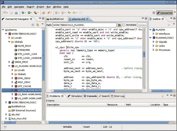
Design entry support includes syntax highlighting, auto-completion and outlines. Under design navigation, instantiation graph on a fully elaborated model, open design unit through instantiation graph, open design unit and open signal declaration via hierarchical paths can be done.
Simulation is performed with the help of a waveform viewer, source back-annotation of simulation values, waveform file import and a built-in simulator. The final design can be analysed with the help of reference and declaration search.
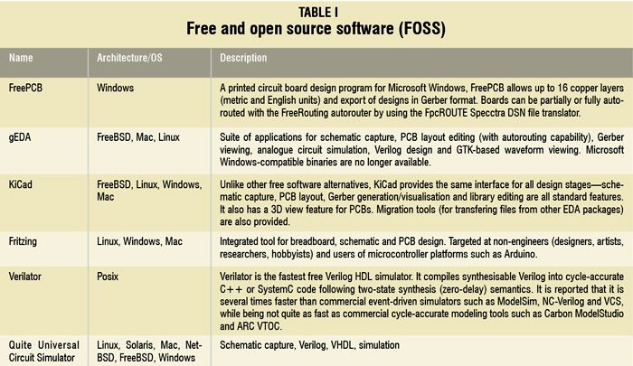
Some other free and open source software (FOSS)
The concept of open source and free sharing of technical information existed even before EDA tools came into the picture. The basic idea of open source software is that it should continuously evolve and develop itself from its initial release with the help of experiences and ideas coming from people using the software. With this kind of community cooperation, those experiences and ideas can be incorporated into future releases. There are a variety of other good open source EDA tools available. Compiled above is a list of them.
The author is a tech correspondent at EFY Bengaluru
