


 This simple single-channel audio amplifier is built around 8-pin IC TDA 7052 and uses only a few other components. Two of these can be used as a stereo amplifier. The amplifier gives 1W output with a power supply of 6V and an 8-ohm speaker.
As shown in its circuit diagram in Fig. 1, pin 1 of TDA7052A (IC1) is connected to four 1.5V batteries to get 6V supply. Electrolytic capacitor C1 (100µF, 25V) and a ceramic capacitor C3 (0.01µF) are used as noise filters.
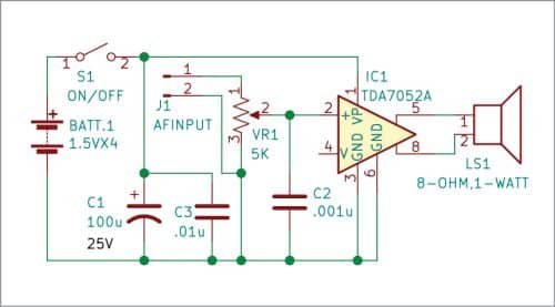

Pin 2 of TDA7052A is the audio signal input pin that is connected to 5k potentiometer (pot) VR1. Audio input is given at pin 2 of IC1 through 2-pin connector J1 and pot VR1, which is used as volume control. Output pins 5 and 8 of the IC are connected to 8-ohm, 1W speaker LS1.
 Construction and testing
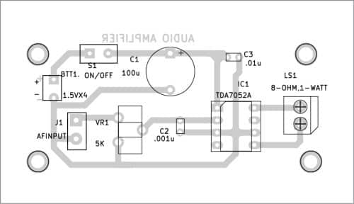
An actual-size PCB layout for the audio amplifier is shown in Fig. 2 and its component layout in Fig. 3. After assembling the circuit on PCB, or on a small Veroboard of about 5x7cm, enclose it in a suitable plastic box. Use an 8-pin socket for the IC, which may be placed in the middle of Veroboard and gently soldered using a small 15W soldering iron.
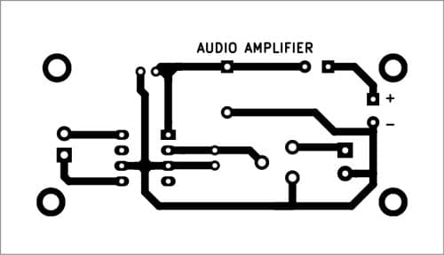
Solder two 2-pin connectors, one for audio input and another for loudspeaker connections. Solder the remaining components on the PCB or Veroboard as per circuit diagram. Mount the IC on the 8-pin socket last of all. Connect the 6V battery and speaker LS1 as shown in Fig. 1.
After switching on the circuit, take a small metal screwdriver and gently touch at the 2-pin AF input connector terminal J1. You should hear a humming sound from the speaker. Connect one end of mono audio jack to terminal J1 on the PCB and the other end to a headphone output of your mobile or laptop/computer or MP3 audio source.
Move the shaft of potentiometer VR1 to middle position. If you hear a noise-free sound from the speaker, it means the amplifier is working and ready to use.
Download PCB and Component Layout PDFs: click here
Raj K. Gorkhali is an electronics hobbyist and a regular contributor to EFY