


Here is a simple audio amplifier circuit based on TDA2050 IC. This amplifier can deliver an output power of around 15W for an 8-ohm load, 18W speaker with 18V DC power supply.
Circuit and working
The circuit diagram of the TDA2050-based 15W audio amplifier is shown in Fig. 1.
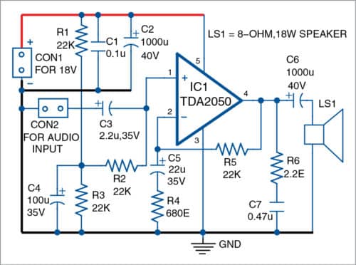
TDA2050 is a 5-pin IC. Pin 1 of the IC is for a non-inverting input. It is connected to ground through resistors R2 and R3. Its pin 2 is an inverting input pin, which is connected to ground through a resistor (R4) and capacitor (C5) network. Pin 3 is directly connected to ground.
Pin 4 is the output pin of the IC where an 8-ohm speaker is connected through C6. Pin 4 is also connected to ground through R6 and C7 in series. Pin 5 is connected to positive 18V power supply.
Working of the amplifier is simple. First, connect audio input from the audio source such as laptop or cellphone across connector CON2. You will hear the amplified audio signal through speaker LS1. (Volume control is not included here; volume can be controlled from the audio source.)
Construction and testing
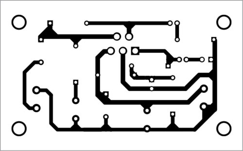
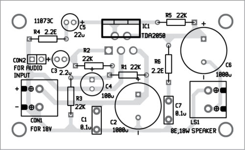
You can construct the circuit on a veroboard, breadboard or PCB. An actual-size PCB layout of the TDA2050-based audio amplifier is shown in Fig. 2 and its components layout in Fig. 3. Place the components on the veroboard or PCB, and solder these using a 25W soldering iron. Use proper connectors for input and output terminals, and a suitable pair of wires for connections to positive and ground terminals of the power supply. Use a suitable heat-sink for TDA2050.
After assembling the circuit on the PCB, enclose it in a suitable box. Fix CON1 on the front panel for the power supply.
Connect 18V power supply to the circuit. Connect the 8-ohm, 18W speaker across LS1. Now, take a metal screwdriver and gently touch C3. You will hear a humming sound coming from the speaker. If so, amplifier is working and ready to use.
Download PCB and component layout PDFs: Click here
Raj K. Gorkhali is an electronics hobbyist and a regular contributor to EFY
This amplifier can’t deliver 15watts @ 8 ohms on 18volts supply. At 24 Volts , 4 ohms load it can deliver max 7 watts and increasing the voltage further will give higher power.