


During our working hours, we all need a refreshing breath of fresh air on our table. Imagine being able to obtain it with the help of a fridge magnet! To enhance it further, you also have a small LED light that switches on while the fragrance is sprayed.
A 2 way operation module is presented wherein by activating the reed switch, a Spray and a Light assembly can be put ON for a duration of 3-5 seconds. In the second choice, where a switch button is employed, the spray stops (after 3-5 seconds) but the LED continues to glow. This can actually double up as a Night Bedside Lamp cum Room Freshener with your favourite choice of scent.
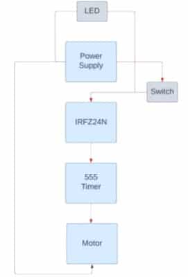
The proposed setup is used as a combined spray and light assembly. Figure 1 shows the author’s prototype of the entire setup. Figure 2 represents the block diagram of the Project.

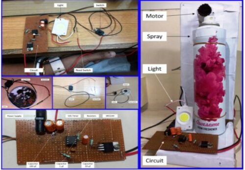
The motor used in the proposed setup is a modified motor. We have used the gear combination found in Home Miller’s 250V motor. We applied that gear combination on a 4000 RPM 12V DC motor and attached one round-end effector. Our purpose for it was to activate the Room Freshener by giving one full rotation to the motor. Torque was the main reason to choose Miller’s motor’s gear combination.
We used 555 Timer IC, which is a popular integrated circuit (IC) that is widely used in electronic circuits for timing and oscillator applications. The IC consists of comparators, flip flops, resistors, and transistors, all integrated onto a single chip. It is available in different packages, including DIP (dual in-line package) and surface mount versions, making it easy to use in various circuit designs.
Additionally, IRFZ244, a specific model of a power MOSFET (Metal-Oxide-Semiconductor Field-Effect Transistor) that is commonly used in electronic circuits for switching applications, is used for switching. It is commonly used in applications where high power switching is required, such as motor control, power supplies, inverters, and amplifiers.
We used a Reed switch as a secondary switch, which is also known as a Reed contact. It is an electrical switch that operates based on the magnetic field. It is made up of two ferromagnetic reed blades enclosed in a glass tube filled with an inert gas. When no magnetic field is present, the reed blades remain separated, and the switch is in an open state, which means it does not conduct electric current. However, when a magnetic field is applied (in the present case using the fridge magnet) near the reed switch, the magnetic force causes the reed blades to attract and make contact with each other, closing the switch and electric current flows. Figure 3 shows the working principle of a reed switch.
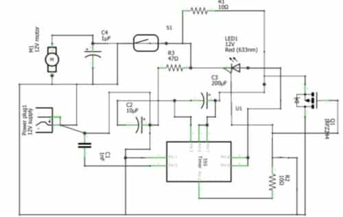
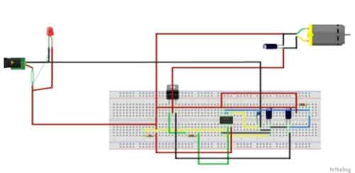
The Circuit is very simple to operate. You can refer to figure 3 for the Circuit diagram and figure 4 for the connection of the proposed solution.
Table 1
|
Components |
Amount |
Description |
|
555 Timer IC |
Rs. 8 |
IC that controls the ON-OFF signals |
|
IRFZ244 |
Rs. 32 |
Power Mosfet |
|
Capacitors |
Rs. 40 |
High Initial torque |
|
Resistors |
Rs. 30 |
Biasing |
|
Modified Motor |
Rs. 450 |
To activate the Room Freshener by press |
|
Switch |
Rs. 18 |
To On and Off circuit |
|
Reed Switch |
Rs. 19 |
Power On or Off using magnet |
|
LED |
Rs. 9 |
To Light up |
|
12 V DC Adapter |
Rs. 199 |
To power up the circuit |
Total: 805/-
Working
Upon activating any of the switching techniques, the room freshener will be dispensed once, simultaneously coinciding with a single rotation of the motor. Let us examine the step by step process.
- The motor is interfaced with the power supply using a MOSFET and a 555 Timer IC. The switch and reed switch are connected in parallel, such that either of them in a high state will activate the circuit. One terminal of the switches is linked to the positive terminal of the power supply with a resistor (47 KΩ), while the other terminal is connected to Pin 2 through capacitor (10 uF), which corresponds to the Trigger Pin of the 555 Timer IC.
Pin 8 of the 555 Timer IC is connected to the positive terminal of the power supply, while Pin 1 is connected to the negative terminal. The Discharge Pin (Pin 7) and the Threshold Pin (Pin 6) of the 555 Timer IC are connected through a resistor (10 KΩ), and a capacitor (200 uF) is placed between Pin 6 and Pin 1.
- The Output Pin (Pin 3) of the 555 Timer IC is connected to the Gate Pin of the IRFZ244. A pull-down resistor (10 KΩ) is added between the Gate Pin of the IRFZ244 and the Ground Pin (Pin 1) of the 555 Timer IC. The Source Pin of the IRFZ244 is also connected to the Ground of the 555 Timer IC (Pin 5) through a capacitor (0.001 uF). The Drain Pin of the IRFZ244 is linked to the positive terminal of the power supply, and the motor is connected between the Drain Pin of the MOSFET and the negative terminal of the power supply with a capacitor (100 uF).
To achieve a specific delay that allows the motor to complete one rotation, resistors and capacitors are incorporated into the circuit. The timing formula for the 555 Timer IC in monostable mode, t = 1.1 × R1 × C1, provides the desired delay time for a one-time turn-on event.
An LEDlight is integrated into the system to indicate the circuit’s state and also to provide a source of light in case the system is kept in darkness.
On a conclusive note, it is a wonderful personalized low cost alternative to the existing choices available in the market.