


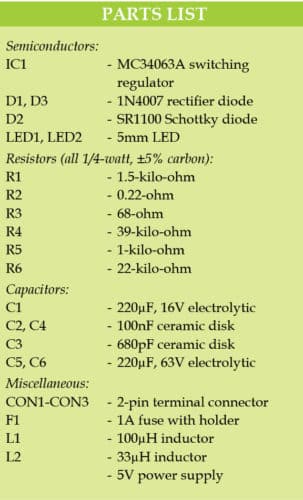
 This circuit provides a straightforward and cost-effective solution to provide 48V DC for phantom power settings such as those found in mixers, mic preamps, and telecom equipment. While 24V and 48V supplies are ubiquitous in these circuits, they are generally expensive and difficult to get.
On the other hand, 5V DC supplies are inexpensive and widely available. This setup demonstrates how to use the common MC34063A IC to convert a 5V DC input into the 48V DC required.
Circuit and Working
The circuit diagram of the 5V DC to 48V DC converter is shown in Fig. 1. It is built around boost/buck/inverting switching regulator MC34063A (IC1), two rectifier diodes 1N4007 (D1 and D3), Schottky diode SR1100 (D2), two 5mm LEDs (LED1 and LED2), two inductors (L1 and L2) and a few other components.


Input power supply ranging from 5V to 7V can be applied to connector CON1. Fuse F1 protects the circuit from any continuous over-current input. Diode D1 protects the circuit from reverse input voltage. Resistor R2 limits the maximum switching current to around 1.5A, as per relationship:
Ipeakmax = 0.3V/R2
Resistor R3 limits the current for the inbuilt driver transistor of IC1. This current should be below 100mA. Operating frequency of MC34063A is in the range of 40kHz to 60kHz, and depends mainly on capacitor C3. Inductor L1 is in the range of 100µH to 150µH for current above 1.8A.
Output voltage is around 48V and can be adjusted with R4. It can be calculated using the approximate relationship:
Vout = 1.25Vx(1+R4/R5)
Output current is up to around 50mA, which is enough for several applications including microphone amplifiers. Voltage on pin 5 of IC1 should be equal to internal reference voltage or around 1.25V (1.21V to 1.29V). Schottky diode D2 should preferably be rated at least 100V. Schottky or ultrafast diode can either be SB1A0, SR1100, SS110 or SR180.
C4 and C5 are the first filtering capacitors. Ripples at OUTPUT1 are around 50mV at 50mA load, which may be too high for some applications. So, second output (OUTPUT2) is provided after LC filter. L2 (usually from 22µH to 220µH for current above 100mA) and C6 produce additional filtration of the voltage produced by the DC-to-DC converter.
We can use both the outputs, OUTPUT1 and OUTPUT2, at the same time under the condition that total current is below 60mA. The circuit does not need any adjustment.
Construction and Testing
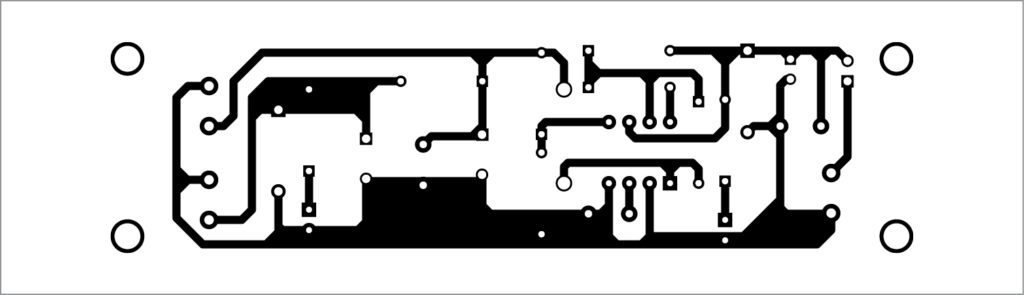
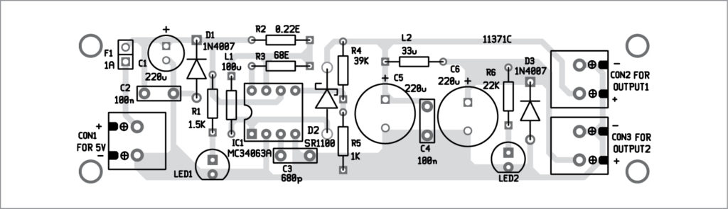
A PCB layout of the DC-to-DC converter is shown in Fig. 2 and its components layout in Fig. 3. After assembling the circuit on the PCB, connect the 5V regulated power supply across CON1. Connect LED1 and LED2 on the front panel to indicate power status.
Additional Considerations
- Efficiency: The efficiency of the MC34063A varies depending on load conditions and component choices. To achieve peak performance, it is recommended that efficiency be measured during testing.
- Thermal Management: Depending on the load and ambient circumstances, the circuit may produce heat. To maintain reliability, the temperature must be monitored and heat sinks installed as needed.
- Alternative ICs: While the MC34063A is appropriate, other boost converter ICs (such as the LM2577 or XL6009) may offer greater efficiency and ease of use, particularly in more demanding applications.
- PCB Design Tips: To reduce noise and improve performance, ensure adequate grounding and minimize trace length. Consider employing vias for power distribution to keep low resistance lines.
Download PCB and component layout PDFs: click here
Petre Tzv Petrov was a researcher and assistant professor in Technical University of Sofia (Bulgaria) and expert-lecturer in OFPPT(Casablance), Kingdom of Morocco. Now he is working as an electronics engineer in the private sector in Bulgaria.
Nice idea , I need more information about it .
I want the output voltage to be stepped up to 110v from 24v and current should be 2 amps . Can you suggest some ideas using this circuit.
Vce of 34063A output transistor is rated for 40V max. So this circuit can be used for output voltage less than 40V, by the diode drop and the output ripple voltage.
Hii Sir, This is vijay. I am an Engineering Student. We have microprojects . So we decided to do your project . So you have uploaded the pdf format of pcb layout . But i need Gerber file format . Kindly help me
Super
If rather than designing PCB from layout if I directly use wire on zero PCB, will my circuit get complicated?
Yes it work
You have to do some hardwork
Sir I get only
18V at output
What to do now
Where can we find a 0.22 ohm Resistor in mumbai?
can anyone please write the function for each of the component.
Read DATA SHEET of each component
Hello,
I am not an engineer, but can this design affect the audio sampling frequency of 96kHz? Somewhere I have read that if the the switch of the regulator is below the desired audio sampling frequency it will degrade the performance of the sampled signal. The datasheet of MC34063A states the max sampling frequency is 100kHz. If this is true, will this regulator and whole design be enough for 24bit/96kHz audio recording with microphone?
Thank you.
Please … which PCB software you used to design the PCB?
Thank you very much
We are using customised gEDA software
bạn có thể cho mình biết rõ hơn về nguyên lý hoạt động của mạch này được không ạ
Xin chào, tất cả thông tin được cung cấp trong bài viết. Nếu cần bất kỳ thông tin cụ thể, xin vui lòng trả lời.
Let me ask why there are two outputs
can you tell me more about the function and duty of each component please help me?
How does mc34063 work in the above circuit
Can I ask if the circuit is like a backup power switch that uses a role
can this do by simulation?
can I get more information about this project plzzz
Kindly elaborate your query.
are you did this project if did please tell me
How can we increase current up to 500 mA for 40V output. If yes can you help me with the range of Inductor value to be used.
Sadly, this IC isn’t suitable for use at 48V output – it’s practical maximum is about 36V. There are other, better, simpler circuits for 48V phantom supplies. Mine uses a few discrete transistors and an inductor, and will provide up to 2A at precisely 48V with a ripple of ~220µV at full load. It costs less to build than the price of the Motorola IC you’re mis-using!
hi ı think inductor position wrong! is someone test this circuit?
What is the current rating of L1?
I think L1 requires a larger package than your layout suggests.