





Need to control multiple appliances but avoid having a switch for each? Here’s a ‘low’ complexity circuit which will take about ‘6 hours’ to build and cost you less than ₹1100. You will end up with a 2-push button controller for managing up to 16 appliances!
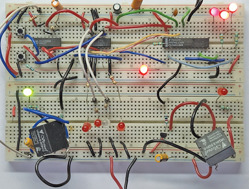
How do you choose one appliance out of many without a separate switch for each? This project does it with just two push buttons: one to step up through the channels and another to step down. A CD4029 up/down counter keeps track of the selected channel, and a 74LS154 4-to-16 line decoder turns the count into one active output, with four light-emitting diodes (LEDs) showing the selected channel in binary. A CD4093 quad NAND Schmitt-trigger IC gives clean button pulses, while BC557 transistors drive 16 individual 5V relays, so the chosen 230V appliance switches on with the low-voltage electronics safely isolated from the mains. It uses only common logic ICs and no microcontroller, which makes it a compact, low-cost introduction to counters, decoders, and relay switching. Fig. 2 shows the author’s breadboard prototype.
What will you learn?
- How to build a multi-channel digital control circuit using logic ICs, push buttons, counters, decoders, transistors, and relays.
- How a Schmitt-trigger NAND gate removes switch bounce and gives one clean pulse per button press.
- How a 4-bit binary count is converted into 16 individual outputs by a decoder.
- How active-low outputs drive positive-negative-positive (PNP) transistors to energise relays.
- How a 5V electronic circuit can safely switch 230V AC appliances through relay isolation.
How it works
The circuit has two main units: the control unit and the relay/appliance switching unit. The circuit diagram is shown in Fig. 3.

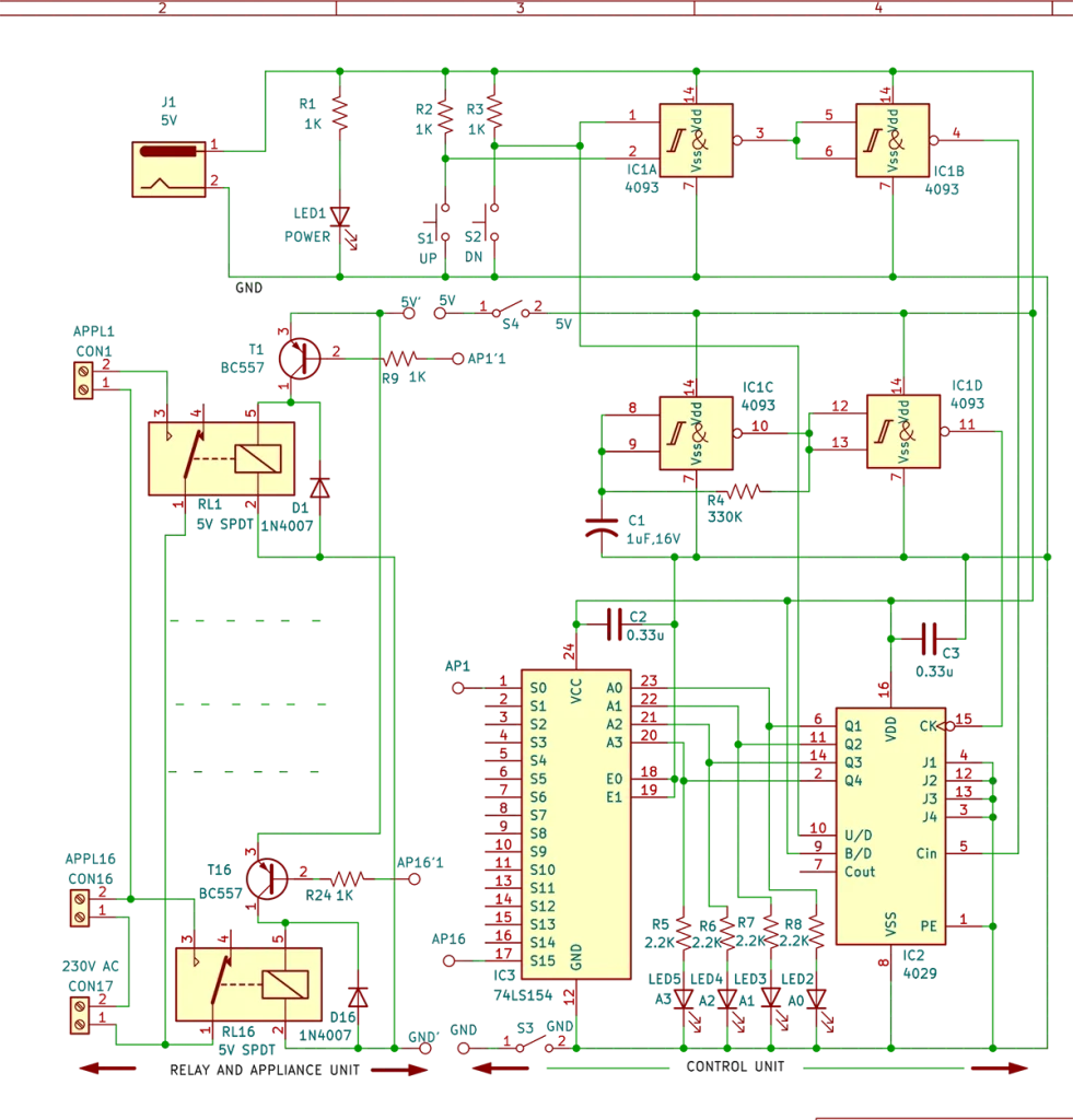
EFY Note. Fig. 3 shows only two appliance channels (APPL1 and APPL16). The remaining channels, APPL2 to APPL15, with their relays (RL2-RL15) and transistors (T2-T15), are identical and are not shown.
Control unit
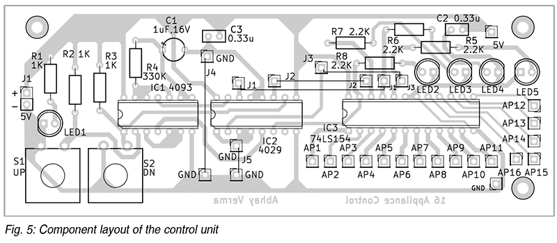
This part is built around IC1 (CD4093), IC2 (CD4029) and IC3 (74LS154). Switches S1 (increment) and S2 (decrement) are used to select the required appliance. Resistors R2 and R3 set the required logic levels at the inputs. When either push-to-on switch is pressed, its signal goes to the Schmitt-trigger NAND gates IC1A and IC1B.
The Schmitt-trigger gates remove the unwanted transitions caused by mechanical contact bounce, so each press produces one clean logic pulse instead of several false ones. The remaining gates, IC1C and IC1D, together with C1 and R4, provide a continuous pulse and make sure the counter triggers reliably.
The clean pulses go to IC2 (CD4029), which is configured as an up/down counter. Pressing S1 increases the count by one, and pressing S2 decreases it by one. The four counter outputs are the selected channel in binary form. Four bits represent 16 states (S0 to S15), so up to 16 channels can be selected.
The 4-bit count is fed to the address inputs (A0 to A3) of IC3, the 74LS154 decoder. The decoder converts the count into one of 16 individual outputs, AP1 to AP16, which are active-low. As the counter changes, the decoder selects AP1, AP2, AP3, and so on up to AP16. For example, the count 0011 selects AP4, and pin 4 of IC3 goes low. LED2 to LED5 show the binary count so you can see which channel is selected (see the table).
| Bill of materials | ||||
| Reference | Component | Value/Type | Quantity | Cost (₹) |
| IC1 (IC1A-IC1D) | Quad 2-input NAND Schmitt trigger | CD4093 | 1 | 33 |
| IC2 | Presettable up/down counter | CD4029 | 1 | 43 |
| IC3 | 4-line-to-16-line decoder/demultiplexer | 74LS154 | 1 | 120 |
| T1-T16 | PNP transistor | BC557 | 16 | 29 |
| RL1-RL16 | Relay | 5V SPDT | 16 | 640 |
| LED1-LED5 | LED | 5mm | 5 | Miscellaneous (~235) |
| D1-D16 | Rectifier diode | 1N4007 | 16 | |
| R1-R3, R9-R24 | Resistor | 1kΩ, ¼W, 5% | 19 | |
| R4 | Resistor | 330kΩ, ¼W, 5% | 1 | |
| R5-R8 | Resistor | 2.2kΩ, ¼W, 5% | 4 | |
| C1 | Electrolytic capacitor | 1µF, 16V | 1 | |
| C2, C3 | Ceramic disc capacitor | 0.33µF | 2 | |
| S1, S2 | Switch | Push-to-on | 2 | |
| S3, S4 | Switch | On/off | 2 | |
| J1 | Connector | 2-pin | 1 | |
| CON1-CON17 | Connector | 2-pin | 17 | |
| – | Jumper wires | – | As needed | |
| APPL1-APPL16 | Appliance | 230V AC, with 2-pin connector | 16 | Not included |
| – | Power supply | 5V adaptor | 1 | Not included |
| Estimated total | 1100 | |||
| Output status of decoder LEDs | ||||
| Appliance | Decoder Output (A3 A2 A1 A0) | Connect | Transistor/Relay | Appliance on |
| AP1 | 0000 | AP1 to AP1′ | T1 ON, RL1 energised | APPL1 |
| AP2 | 0001 | AP2 to AP2′ | T2 ON, RL2 energised | APPL2 |
| AP3 | 0010 | AP3 to AP3′ | T3 ON, RL3 energised | APPL3 |
| AP4 | 0011 | AP4 to AP4′ | T4 ON, RL4 energised | APPL4 |
| AP5 | 0100 | AP5 to AP5′ | T5 ON, RL5 energised | APPL5 |
| AP6 | 0101 | AP6 to AP6′ | T6 ON, RL6 energised | APPL6 |
| AP7 | 0110 | AP7 to AP7′ | T7 ON, RL7 energised | APPL7 |
| AP8 | 0111 | AP8 to AP8′ | T8 ON, RL8 energised | APPL8 |
| AP9 | 1000 | AP9 to AP9′ | T9 ON, RL9 energised | APPL9 |
| AP10 | 1001 | AP10 to AP10′ | T10 ON, RL10 energised | APPL10 |
| AP11 | 1010 | AP11 to AP11′ | T11 ON, RL11 energised | APPL11 |
| AP12 | 1011 | AP12 to AP12′ | T12 ON, RL12 energised | APPL12 |
| AP13 | 1100 | AP13 to AP13′ | T13 ON, RL13 energised | APPL13 |
| AP14 | 1101 | AP14 to AP14′ | T14 ON, RL14 energised | APPL14 |
| AP15 | 1110 | AP15 to AP15′ | T15 ON, RL15 energised | APPL15 |
| AP16 | 1111 | AP16 to AP16′ | T16 ON, RL16 energised | APPL16 |
Note: Always connect 5V to 5V′ and GND to GND′. Use switches S3 and S4 to turn the appliances on or off.
Relay and appliance switching unit
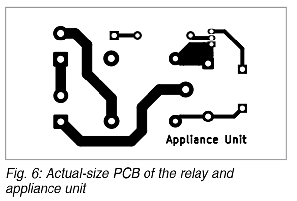
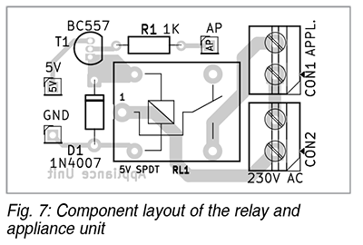
This part uses 16 BC557 transistors (T1-T16) as driver stages, 16 SPDT relays (RL1-RL16) and 16 flyback diodes (D1-D16). Each decoder output drives its own transistor, which energises its 5V relay. A 1N4007 diode across each relay coil protects the transistor from the voltage spike produced when the relay switches off. The relay contacts isolate the 5V control circuit from the 230V AC load, and each relay can switch its appliance within the relay’s rated capacity.
Using S1 and S2, you select one appliance at a time, and LED2 to LED5 indicate the selection. The table lists the corresponding output status.
Construction
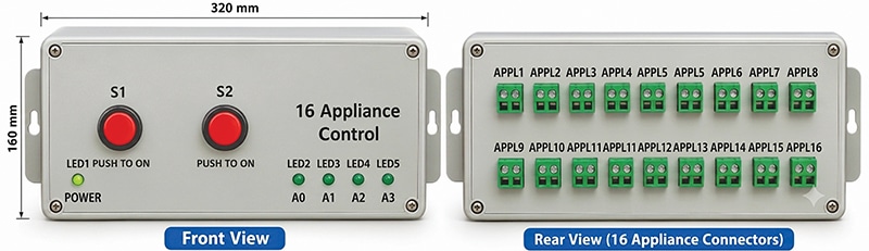
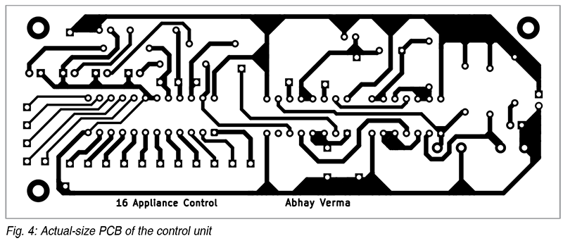
Assemble the circuit on either a custom-designed PCB or a general-purpose PCB. Connect terminals AP1 through AP16 of the control unit to the corresponding AP1’ through AP16’ connections on the relay and appliance units. Ensure you also connect the common 5V and GND lines. Once assembly is complete, house the components in the recommended enclosure and power on the system for testing.
Testing
EFY note. Before connecting any 230V AC load, test the circuit with 5V DC only.
- Check that the 5V supply voltage is correct and that there is no short circuit.
- Power on the circuit and check that the control section works.
- Keep S3 and S4 off.
- Press S1 and S2 and check that the LEDs count up and down correctly.
- Check that LED2 to LED5 show the selected channel (refer to the table).
For example, to enable APPL16:
- Power the circuit with 5V DC.
- Press S1 (up) or S2 (down) until LED2 to LED5 all glow, indicating 1111.
- Connect AP16 to AP16′, 5V to 5V′ and GND to GND′, and connect APPL16 to CON16.
- Connect the 230V AC supply to CON17.
- Switch S3 and S4 on. This selects output S15 of IC3, which corresponds to APPL16.
- IC3 pulls its S15 output (pin 17) low, which turns T16 on and energises RL16.
- The relay contacts connect AP16 to AP16′ and switch APPL16 on.
- To switch APPL16 off, turn S3 or S4 off. S4 can be used to switch off any appliance at any time.
Safety note
The 230V AC section is hazardous. Use proper insulation, protection, rated components, a secure enclosure, and earthing. Mains wiring and testing must be done by a qualified person.
Troubleshooting
If a channel does not work, check the 5V supply, IC orientation, push-button connections, and the wiring around the counter and decoder. Also inspect the BC557 transistors, relay coils, flyback diodes, and indicator LEDs. Test each channel individually and check that the counter and decoder outputs change correctly.
Applications
This circuit can be adapted for lab equipment control, demonstration panels, and digital electronics teaching projects.
S.C. Dwivedi is an electronics enthusiast and circuit designer at EFY