


The AC level 2 charger platform features a low standby power stage, control interfaces, and applications for residential and commercial settings, ensuring energy management and safety.
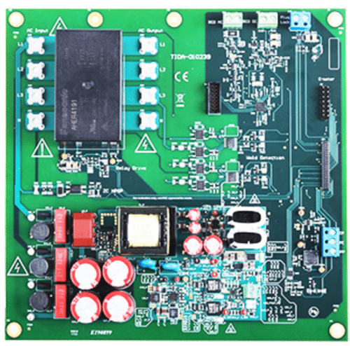
Electric vehicle service equipment (EVSE) ensures safe power delivery to electric vehicles from the grid. The control system of an EVSE includes an auxiliary power stage, a high-power off-board AC/DC conversion stage (specific to DC charging stations), energy metering, AC and DC residual current detection, isolation monitoring, relays and contactors with their drivers, two-way communication via a single wire, and interfaces for service and users. TIDA-010239, the reference design of AC level 2 charger platform from Texas Instruments (TI) features an ultra-low standby isolated AC/DC auxiliary power stage, converters and linear regulators, a comparator-based control pilot interface compliant with the IEC61851 standard, efficient relay and contactor drives, a plug lock motor driver, a flux gate circuit for AC and DC detection in residual current device (RCD) applications, and isolated line voltage sensing across the relay and contactor.
The applications for these EV charging solutions encompass a wide range of environments and needs. They include industrial fast charging stations for rapid charging, DC wall box chargers for efficient space utilization, and specialized modules for power management and human-machine interface (HMI) at EV charging stations. Additionally, the lineup offers Level 1 residential chargers for home use, Level 2 chargers suitable for both commercial settings and residential properties, and single-phase wireless EV charging stations, providing flexible and innovative charging options across different scenarios.

This device features a range of enhancements designed to optimize energy management and safety in applications. It includes an ultra-low standby UCC28742-based isolated 29-W AC/DC stage that enhances energy efficiency. It also features a supercapacitor backup that can supply up to 7.5 W for three seconds during energy release when AC mains fail. Tight output voltage regulation (less than ±5%) is maintained through low dropouts (LDO) and the high slew rate of the TLV1805 device, which is used for the control pilot interface. Additionally, it boasts ultra-low standby and cost-optimized converters and linear regulators that power up points of load. The DRV8220 current controller is employed to drive high-current relays and contactors, providing thermal protection, residual current detection (RCD) for AC and DC, and plug lock control. Isolated line voltage sensing is achieved using the ISO1212 digital input receiver, which detects welded relays and contactors.
The isolated AC/DC power stage features a multiple output winding flyback stage utilizing the UCC28742 device. This controller employs an optical coupler for constant-voltage (CV) delivery, enhancing the transient response to significant load changes. It achieves constant-current (CC) regulation through primary-side regulation (PSR) techniques. By processing data from the optocoupled feedback and an auxiliary flyback winding, this device ensures precise and high-performance control of the output voltage and current.
TI has tested this reference design. It comes with a Bill of Material (BOM), schematics, assembly drawing, Printed Circuit Board (PCB) layout, and more. The company’s website has additional data about the reference design. To read more about this reference design, click here.

Hi there,
With a range of 0.350 to 0.550 milliohms, the sample and small circuit control board can be attached to a pouch cell battery.
Can I talk to someone about this scenario please?
email via : [email protected]
Yes, with a resistance range of 0.350 to 0.550 milliohms, the sample and a small circuit control board can be attached to a pouch cell battery. This low resistance indicates good electrical conductivity, which is essential for minimal voltage drop and efficient current flow in applications involving pouch cell batteries. This setup is typically used in battery management systems to monitor and control the battery’s performance, ensuring safety and efficiency.