


Air pollution is a critical concern in modern living environments, particularly in enclosed spaces such as homes, offices, factories, and laboratories, where prolonged exposure to harmful gases presents serious health risks. Continuous air quality monitoring is therefore essential to maintain safe and healthy indoor conditions. Here we detail the design and implementation of a compact, low-cost, smart air-quality monitoring system based on the Arduino Nano platform.
The system employs an MQ135 gas sensor to detect harmful gases in ambient air continuously. Based on predefined threshold levels, air quality is categorised as good, poor, very poor, or toxic and displayed on a 16×2 LCD with an I²C interface. An audible alert is generated by a buzzer connected to a digital output pin, which activates when the air quality exceeds safe limits.
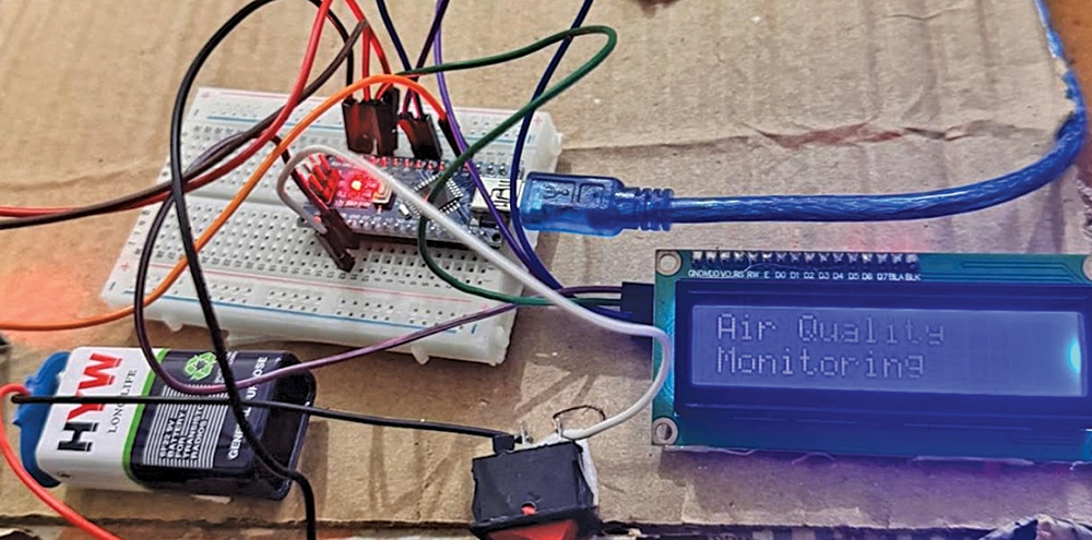
Although a standardised air quality index (AQI) is not computed, the system effectively indicates pollution levels and provides real-time alerts. Fig. 1 shows the system prototype, and the Bill of Materials table lists the required components.

POC Video Tutorial
| Bill Of Materials | |
| Compnents | Quantity |
| Arduino Nano (MOD1) | 1 |
| 16×2 LCD I2C (MOD2) | 1 |
| MQ135 (S1) | 1 |
| Buzzer (B1) | 1 |
| USB cable | 1 |
| Jumper wires | 40 |
| Breadboard | 1 |
| 9V battery (optional) | 1 |
Recommended: Buy electronics components online from trusted suppliers.
Air Quality Monitoring System Circuit
The circuit diagram of the Arduino Nano–based air quality monitoring system is shown in Fig. 2. The system is built around an Arduino Nano (MOD1), an MQ135 gas sensor module (S1), a 16×2 LCD with an I²C interface (MOD2), a buzzer, and a small number of additional components.

