


We come across Liquid Crystal Display (LCD) displays everywhere around us. Computers, calculators, television sets, mobile phones, and digital watches use some kind of display to display the time.
Table of Contents
An LCD screen is an electronic display module that uses liquid crystal to produce a visible image. The 16×2 LCD display is a very basic module commonly used in DIYs and circuits. The 16×2 translates a display of 16 characters per line in 2 such lines. In this LCD, each character is displayed in a 5×7 pixel matrix.


16X2 LCD Display Pinout Diagram

|
Pin No. |
Function |
Name |
| 1 |
Ground (0V) | Ground |
| 2 |
Supply voltage; 5V (4.7V – 5.3V) |
Vcc |
| 3 |
Contrast adjustment; the best way is to use a variable resistor such as a potentiometer. The output of the potentiometer is connected to this pin. Rotate the potentiometer knob forward and backward to adjust the LCD contrast. |
Vo / VEE |
| 4 | Selects command register when low, and data register when high | RS (Register Select ) |
| 5 | Low to write to the register; High to read from the register | Read/write |
| 6 | Sends data to data pins when a high to low pulse is given; Extra voltage push is required to execute the instruction and EN(enable) signal is used for this purpose. Usually, we set en=0, when we want to execute the instruction we make it high en=1 for some milliseconds. After this we again make it ground that is, en=0. | Enable |
| 7 | 8-bit data pins | DB0 |
| 8 | DB1 | |
| 9 | DB2 | |
| 10 | DB3 | |
| 11 | DB4 | |
| 12 | DB5 | |
| 13 | DB6 | |
| 14 | DB7 | |
| 15 | LED Backlight VCC (5V) | Led+ |
| 16 | LED Backlight Ground (0V) | Led- |
RS (Register Select)
A 16X2 LCD has two registers, namely, command and data. The register select is used to switch from one register to other. RS=0 for the command register, whereas RS=1 for the data register.
Command Register: The command register stores the command instructions given to the LCD. A command is an instruction given to an LCD to do a predefined task. Examples like:
- initializing it
- clearing its screen
- setting the cursor position
- controlling display etc.
Processing for commands happens in the command register.
Data Register: The data register stores the data to be displayed on the LCD. The data is the ASCII value of the character to be displayed on the LCD. When we send data to LCD, it goes to the data register and is processed there. When RS=1, the data register is selected.
Important Command Codes for 16×2 LCD
| Sr.No. | Hex Code | Command to LCD instruction Register |
| 1 | 01 | Clear display screen |
| 2 | 02 | Return home |
| 3 | 04 | Decrement cursor (shift cursor to left) |
| 4 | 06 | Increment cursor (shift cursor to right) |
| 5 | 05 | Shift display right |
| 6 | 07 | Shift display left |
| 7 | 08 | Display off, cursor off |
| 8 | 0A | Display off, cursor on |
| 9 | 0C | Display on, cursor off |
| 10 | 0E | Display on, cursor blinking |
| 11 | 0F | Display on, cursor blinking |
| 12 | 10 | Shift cursor position to left |
| 13 | 14 | Shift the cursor position to the right |
| 14 | 18 | Shift the entire display to the left |
| 15 | 1C | Shift the entire display to the right |
| 16 | 80 | Force cursor to the beginning ( 1st line) |
| 17 | C0 | Force cursor to the beginning ( 2nd line) |
| 18 | 38 | 2 lines and 5×7 matrix |
Displaying Custom Characters on 16X2 LCD
Generating custom characters on LCD is not very hard. It requires knowledge about the custom-generated random access memory (CG-RAM) of the LCD and the LCD chip controller. Most LCDs contain a Hitachi HD4478 controller.
CG-RAM is the main component in making custom characters. It stores the custom characters once declared in the code. CG-RAM size is 64 bytes providing the option of creating eight characters at a time. Each character is eight bytes in size.
CG-RAM address starts from 0x40 (Hexadecimal) or 64 in decimal. We can generate custom characters at these addresses. Once we generate our characters at these addresses, we can print them by just sending commands to the LCD. Character addresses and printing commands are below.
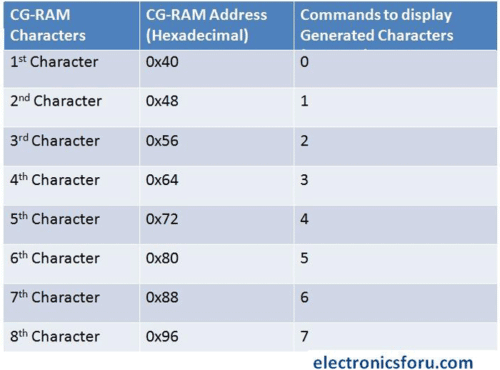
In the table above you can see starting addresses for each character with their printing commands.
The first character is generated at addresses 0x40 to 0x47 and is printed on LCD by just sending a command 0.
The second character is generated at addresses 0x48 to 0x55 and is printed by sending a command 1.
How to Generate Custom Characters in CG-RAM
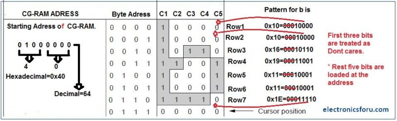
In LCD displays, each character is in a 5×8 matrix. Where 5 is the number of columns and 8 is the number of rows.

Here is a simple example of how to create the letter ‘b’ in CG-RAM.
The Array for generating ‘b’ is char b[7]={0x10,0x10,0x16,0x19,0x11,0x11,0x1E}; That is,
- Send the address where you want to create a character.
- Now create your character at this address. Send the ‘b’ character array values defined above one by one to the data register of the LCD.
- To print the generated character at 0x40. Send command 0 to the command register of LCD. The table below would explain this more clearly-
Interfacing LCD 16X2 with Arduino
LCD modules are very important in many Arduino-based embedded system designs to improve the user interface of the system. Interfacing with Arduino gives the programmer more freedom to customize the code easily.
Any cost-effective Arduino board, a 16X2 character LCD display, jumper wires, and a breadboard are sufficient enough to build the circuit.

For detailed explanation, you can check how to use LCD with Arduino.
Display the LED Brightness on a 16×2 LCD
The combination of an LCD and Arduino yields several projects, the most simple one being LCD to display the LED brightness. All we need for this circuit is an LCD, Arduino, breadboard, a resistor, potentiometer, LED, and some jumper cables. The circuit connections are below.
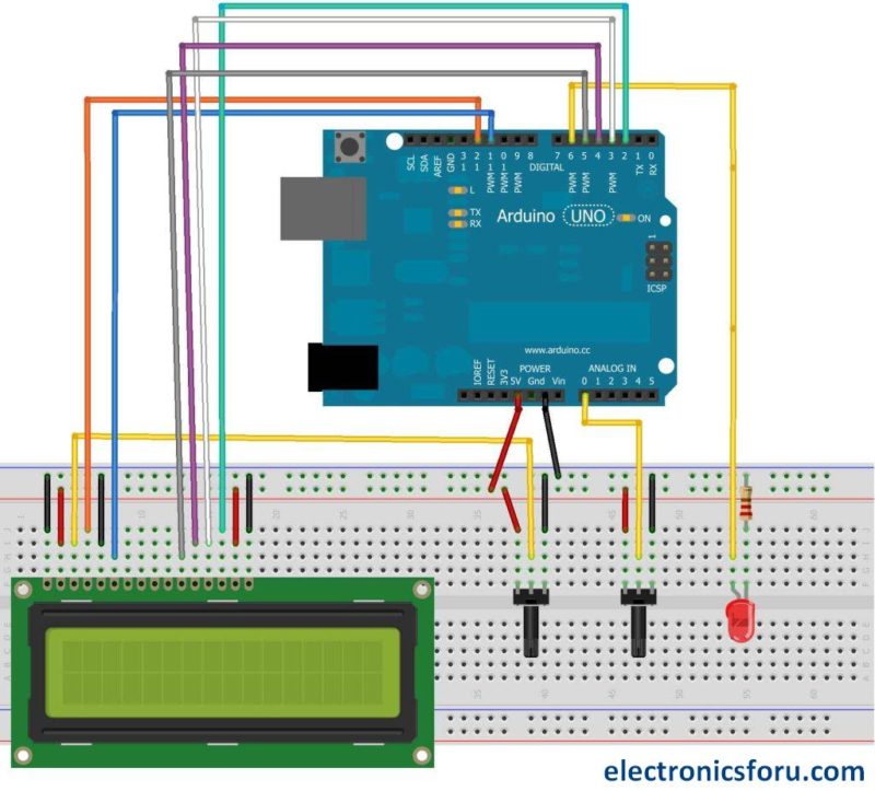
The detailed project is available at displaying the brightness of a LED on an LCD display.
16×2 LCD Display – FAQs
What is a 16×2 LCD display?
A 16×2 LCD display is a liquid crystal display that can show 16 characters in each of its two rows, providing a total of 32 characters of information. It’s commonly used to display alphanumeric information in various electronic devices.
How does a 16×2 LCD display work?
A 16×2 LCD display works by controlling the liquid crystals to either block or allow light to pass through, creating characters and symbols on the screen. It’s controlled by sending data and commands to its controller, which in turn manages the display of information.
What is the pin configuration of a 16×2 LCD display?
A standard 16×2 LCD display has 16 pins, typically organized into two rows of eight pins each. These pins are used for power supply, data communication, and control signals.
What is the purpose of the contrast control in a 16×2 LCD display?
The contrast control adjusts the contrast between the text and the background on the LCD screen. By changing the voltage across the liquid crystals, you can control the readability of the displayed content.
What kind of information can be displayed on a 16×2 LCD display?
A 16×2 LCD display can display a wide range of information, including text, numbers, symbols, and basic graphics. It’s often used to display status information, menu options, sensor readings, and more.
Can I use special characters on a 16×2 LCD display?
Yes, most 16×2 LCD displays support custom character generation. This allows you to create and display your own characters or symbols beyond the standard alphanumeric characters.
What is the backlight in a 16×2 LCD display?
The backlight is a built-in light source that illuminates the LCD screen, making the displayed information visible in low-light conditions. It can be controlled to adjust the brightness of the display.
What are the common applications of a 16×2 LCD display?
16×2 LCD displays are widely used in various applications, including digital clocks, temperature and humidity displays, electronic voting machines, industrial automation, robotics, embedded systems, and more.
Can I change the font size on a 16×2 LCD display?
No, the font size on a standard 16×2 LCD display is fixed. Each character occupies a single cell, and the font cannot be changed. However, some advanced displays may offer larger or smaller font options.
Are there any limitations to using a 16×2 LCD display?
While 16×2 LCD displays are versatile, they have limitations such as limited screen size and resolution, and they might not be suitable for displaying complex graphics or large amounts of information.
Is it possible to display multiple languages on a 16×2 LCD display?
Yes, it’s possible to display multiple languages on a 16×2 LCD display as long as the characters are within the supported character set of the display. You might need to map characters from different languages to the available characters in the display’s memory.
Can I control the cursor position on a 16×2 LCD display?
Yes, you can control the cursor position on a 16×2 LCD display using commands. You can position the cursor at specific coordinates on the screen to control where the next character or information will be displayed.
This article was first published on 21 November 2016 and recently updated on August 2023.
How to power tge LCD? I mean is there any external circuit/battery required to provide power supply to LCD.
Yes.It operates on 5v,so a 5v power supply is needed.
how select 1st line in 16 * 2 lcd display ? if 1st line is selected means it should display anther function?
it provides a valid information useful to aware about the electronic basics…:-)
What is the use of pin back light vcc
&Back light ground
connect them to 5v and gnd to illuminate the lime-colored back light led.
This is useful to read lcd text even in darkness.
it’s better to add in-series 220 ohm resistor to 5v or ground.
i am interfacing 16*2 lcd display and i give the text but it displays only few seconds after there is no text was displayed
why it shows garbage valve some time.
i am interfacing LCD 12864 (128×64)and i give the text but it displays only few seconds after there is no text was displayed please help me in displayin senter of the screen and life span of the text .
There’s difference between character and graphic lcd displays.
48 + 8 in hex is 50. Hex adresses should end at 7f not 96. You started at the right hex address but counted in decimal.
i am interfacing 16*2 lcd display and i give the text but it displays only few seconds after there is no text was displayed