


 This circuit monitors the AC current flowing through an electrical appliance and automatically turns the appliance off when the current goes beyond maximum or minimum threshold levels. If the appliance is drawing very high or very low current than the specified rated current, this indicates that there is a fault with the appliance. This guard is extremely useful where motors are used in the appliance or an equipment.
Circuit and working
The circuit diagram of the appliance guard is shown in Fig. 1. It is built around microcontroller (MCU) ATmega8A (IC1), op-amp LM358 (IC2), 5V voltage regulator 7805 (IC3), 16×2 LCD (LCD1), two transistors BC547 (T1) and 2N2222 (T2), step-down transformer (X1), 12V relay (RL1) and a few other components.
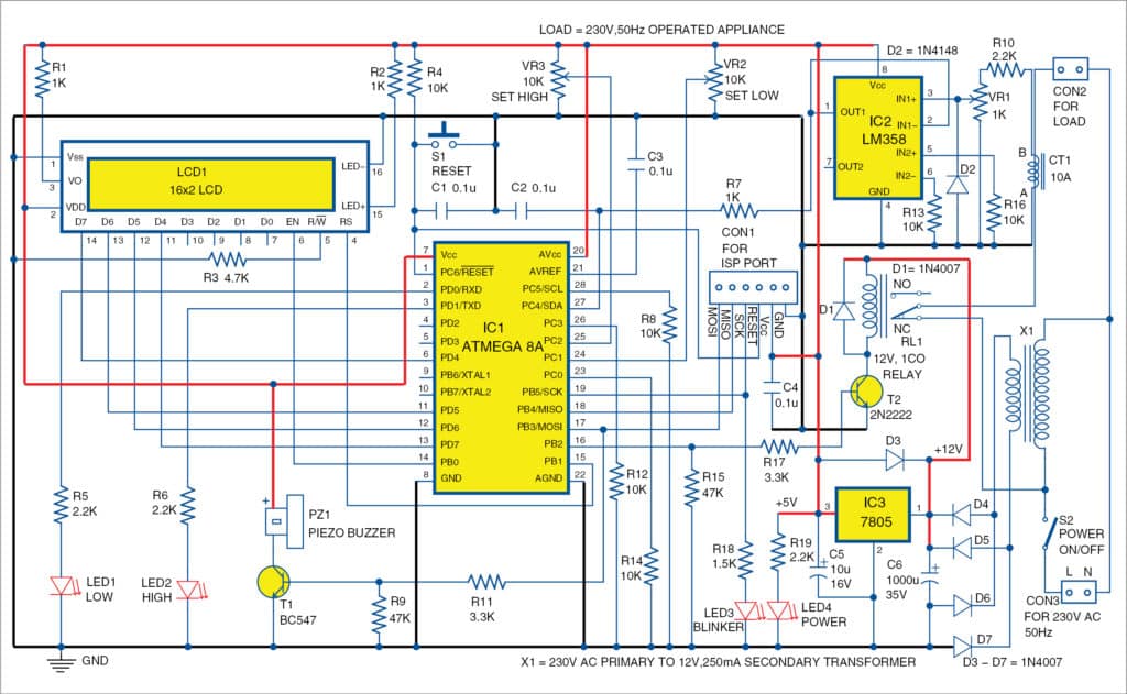
The circuit measures AC current flowing through the appliance/equipment by continuously monitoring the current value, which is also displayed on the LCD. AC current drawn by the appliance is measured using current transformer CT1, which has many turns of wire wound on a circular core. AC current carrying the conductor (say, phase, line or live wire) is passed through the core of CT1, which produces voltage (or EMF) proportional to the current passing through it. Voltage generated is AC in nature, which is available across points A and B. This voltage is fed to op-amp IC2, which is connected as a unity-gain amplifier, through resistor R10, potmeter VR1 and diode D2.

IC2 circuit removes the negative half of the signals received from CT1, so that only positive signals are fed to pin 27 of the MCU for analogue to digital converter (ADC). Internal ADC of the MCU measures the voltage continuously and records peak values, which are displayed on LCD1.
The circuit trips (or switches off the relay) in case current goes beyond the set high value or lower than the set low value. Tripping occurs if either high- or low-current condition continues for around 10 seconds. This protects the appliance from further damage.
Software
The software (applianceguard.c) is written in C language. AVR Studio can be used to generate the hex code (applianceguard.hex) for programming ATmega8A MCU. You can use any suitable programmer to burn the hex code into the MCU. (At EFY Labs, ISP programmer was used for burning the hex code into ATmega8A.)
Delay can be adjusted in the code given below by modifying the value 60 to some other value.
#define MAX_L 60
Download Source Folder
Construction and testing
An actual-size PCB layout of the appliance guard is shown in Fig. 2 and its components layout in Fig. 3. Assemble the circuit on the PCB and connect 12V AC secondary of transformer X1 to the PCB. Connect 230V AC, switch S2, primary of X1, CT1 and the appliance externally using suitable wires.
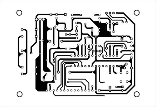

Download PCB and component layout PDFs: click here
Once the circuit assembly is done, write/burn applianceguard.hex file to the MCU using a suitable programmer. Then, mount the MCU on the PCB. It is recommended to use a 28-pin IC base for the MCU. Keep VR1 and VR2 to the minimum and VR3 to the maximum positions.
Now, pass the phase/line wire of the appliance through CT1 and measure the current using a clamp meter, as explained in Calibration section below. Using S2, switch on the circuit and the appliance. Relay RL1 will get energised with a small delay and AC appliance will switch on.
Calibration
Make sure that one end of CT1 as well as VR1 is grounded. Only one line of AC power, phase or live (L) should pass through the current coil.
AC current value is displayed on the first row of LCD1. Initially, value displayed on LCD1 may not be correct. Adjust VR1 slowly till LCD1 shows the value read on the clamp meter.
Adjust VR2 till voltage at pin 24 of IC1 is low (0V) and adjust VR3 till voltage at pin 25 of IC1 is high (5V). Remove the clamp meter after adjustment and calibration.
To adjust the high or maximum limit to trip the relay, adjust VR3 to the required maximum current limit (say, 1.5 times the working current value displayed in the first row). Similarly, to adjust the low or minimum limit to trip the relay, adjust VR2 to the required minimum current limit (say, 0.5 times the working current). Now, the circuit is ready to use.
Once the value crosses the high or low limit, the buzzer will start beeping and the corresponding LED (LED1 or LED2) will start blinking. If blinking continues for more than 10 seconds, the corresponding LED will blink quickly and the relay will switch off, thus protecting the appliance or equipment. Press reset switch S1 to restart the program.
Note. Current transformers are available with various capacities like 10A, 30A, etc, which indicates the maximum current these can measure correctly. Select one with more than the required capacity—preferably double (or more) of the working current range. (Current program can read maximum 50A.)
Caution
Care should be taken while handling 230V AC power supply.
Fayaz Hassan is a manager at Visakhapatnam Steel Plant, Andhra Pradesh. He is interested in MCU projects, mechatronics and robotics.
