


We have designed an Arduino-based GPS Tracker using the NEO-6M GPS Module.
A GPS (global positioning system) tracker utilises satellite signals to accurately determine the location of an object or person in real time. Originally developed by the United States Department of Defense for military applications, GPS technology has become widely accessible for civilian use.
GPS trackers consist of hardware and software components that work together to receive signals from GPS satellites, calculate precise coordinates, and transmit this information to a central server or user device.
They are commonly used in various industries such as transportation, logistics, fleet management, personal safety, and asset tracking. GPS trackers can be installed in vehicles, smartphones, wearable devices, or attached to assets to monitor their movement, location, and other relevant data.
POC Video Tutorial In English
POC Video Tutorial In Hindi
In recent years, the widespread availability of GPS tracking technology has led to its adoption in consumer-oriented applications as well.
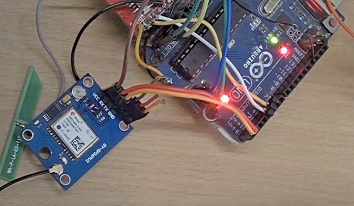
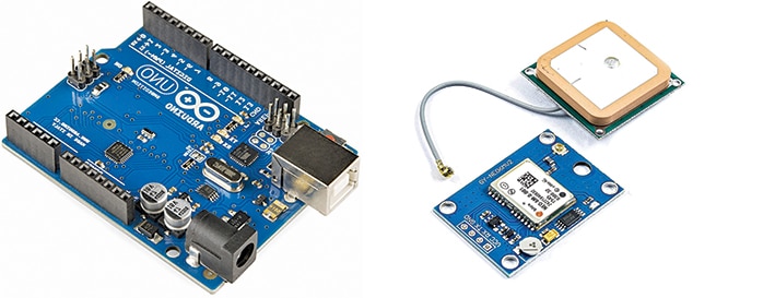
Here, this Arduino-based GPS tracker is designed to be installed in robots and vehicles and programmed according to the needs of people. The author’s prototype is shown in Fig. 1. The components required to build this tracker are listed in the Bill of Materials table. The main components used in this tracker are shown in Fig. 2.
Arduino Board
The Arduino Uno is one of the most popular microcontroller boards in the Arduino line-up. It is based on the ATmega328P microcontroller and provides a simple and accessible platform for electronics enthusiasts, hobbyists, and professionals to create interactive projects.
The heart of the Arduino Uno is the ATmega328P microcontroller, which is responsible for executing the program and controlling the project. It has 14 digital input/output pins. It runs at a 16MHz clock speed and has a USB connection, allowing the code to be uploaded from the computer to the board and communicated with.
| Bill of Materials | |
| Components | Quantity |
| Arduino Uno (MOD1) | 1 |
| GPS module NEO 6M or similar GPS (MOD2) | 1 |
| Jumper wires | 10 |
| USB C adaptor | 1 |
NEO-6M GPS Module
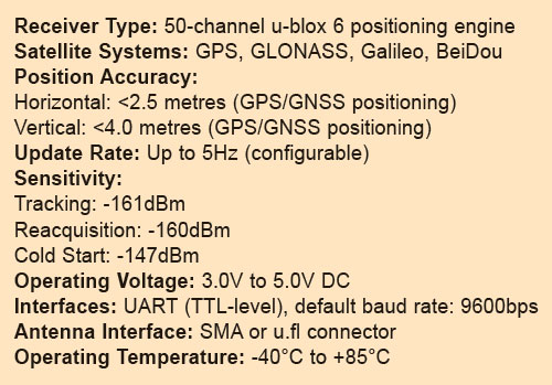
It is a compact, low-cost GPS receiver module widely used in various electronic applications that require accurate positioning and timing information. An introduction to the NEO-6M GPS module, along with its specifications, can be seen in Fig. 3.
Arduino and NEO-6M GPS Module Connection
Fig. 4 shows the circuit diagram of the Arduino-based GPS tracker. It is built around the Arduino Uno (MOD1) and NEO-6M GPS module (MOD2). Pins D2 and D3 of the Arduino Uno board are connected to pins 2 (RX) and 3 (TX) of the NEO-6M GPS module, respectively.
As the GPS module works on the serial peripherals, it can be attached to any software or hardware pin on Arduino. Here, in this design, the software serial pin is used.
The GPS module is powered with the Arduino 5V pin and GND pin, and Arduino is powered from USB on Arduino.
Code for Arduino-based GPS Tracker
The code is created in Arduino IDE. The GPS gives serial data, so here the SoftwareSerial library has been used. Set the RX and TX pins for the SoftwareSerial interface. The baud rate is set as 9600, and next, the data is dumped to the serial port to be seen on the serial monitor screen.
The uploaded source code can be seen on the serial monitor. Fig. 5 shows the raw data code snippet.

The data stream can be observed by opening he serial port. One of the lines might look like: $GPGGA,123519,4807.038,N,01131.000,E,1,08,0.9,545.4,M,46.9,M,,*47 In this example, $GPGGA is the prefix indicating the type of data (in this case, global positioning system fixes the data).
The subsequent fields contain information such as time (123519), latitude (4807.038 N), longitude (01131.000 E), number of satellites in view (08), altitude (545.4 metres), etc.
To decode NMEA sentences in Arduino, libraries like TinyGPS can be used. We just saw a basic example of how TinyGPS might be used to decode a NMEA sentence. Fig. 6 shows the final code’s snippet.
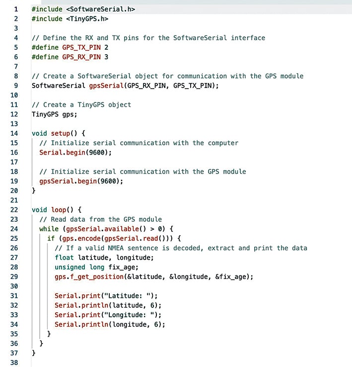
In this code, the TinyGPS library is used to decode NMEA sentences received from the GPS module via SoftwareSerial. Inside the loop() function, characters are continuously read from the GPS module’s serial interface and passed to the gps.encode() function.
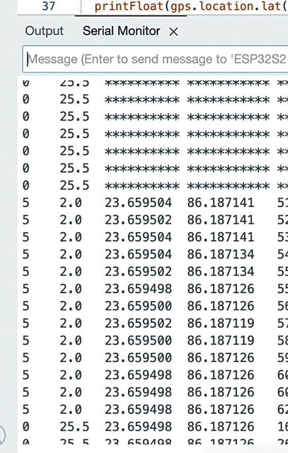
When a complete NMEA sentence is received and successfully decoded, the latitude and longitude are extracted using gps.f_get_position() and printed to the serial monitor.
Testing Arduino Location Tracker
After uploading the source code into the Arduino board and interconnecting the Arduino Uno and NEO-6M module, the circuit is ready to use. Now power the module and open the serial monitor. The location can be mapped in latitude and longitude.
Copy the latitude and longitude to Google Maps to view the location on maps. Fig. 7 shows the serial monitor showing GPS data.
Also, Check other GPS Tracking Projects:
- Smart GPS Tracker using Arduino
- Build Your Own GPS Tracker!
- DIY GPS and GSM Tracking System
- Smallest GPS Tracker
Rajesh Rathakrishnan is an embedded specialist with a passion for technology in IoT. He holds a degree in Bachelor of Engineering and has written extensively on topics ranging from embedded wireless IoT to cloud technologies.