 This is an automatic liquid vending machine based on radio-frequency identification (RFID) system. A fixed amount of liquid can be dispensed by swiping an RFID tag across the RFID reader. An alphanumeric LCD is used to display the operation and instructions for users to follow while dispensing the liquid. This machine could be implemented in organisations like hospitals and colleges (medical, engineering, etc) to provide 24-hour service to customers with no humans involved.
The vending machine has many advantages and is highly beneficial in many ways. Some examples are given below:
- In hospitals, it can be used as a milk vending machine. Patients can buy milk from the vending machine without going to the market.
- In educational organisations, some shops are opened for fixed hours. With this machine, you get 24-hour service.
- At events/functions, this machine can be used to dispense juice of varied flavours.
- In rural areas, this machine can be used to dispense water for a variety of purposes including drinking and watering plants to enhance productivity as well as quality.
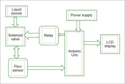
The concept of this project could be useful for hobbyists and designers to further design a rugged-mechanical machine. This DIY article describes programming and interfacing the circuit as per the working prototype without mechanical construction parts. The main components required in this project are listed in the table on next page. The block diagram of Arduino based liquid vending machine is shown in Fig. 1.
Circuit and working
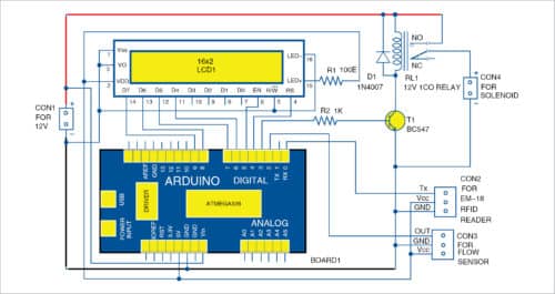
The circuit diagram of Arduino based liquid vending machine is shown in Fig. 2. This project consists of analogue flow sensor, RFID tag, RFID reader, 16×2 LCD, solenoid, Arduino Uno, a single channel relay and a 12V DC power supply.
Analogue water flow sensor
This sensor measures the flow rate of a fluid. It has two openings—one opening for fluid in-take and the other for out-take.
It works on the principle of the Hall effect. The Hall effect is utilised in the flow meter using a small fan/propeller-shaped rotor, which is placed in the path of the liquid flow.
It has three wires: red wire for supply voltage, black wire for ground and a yellow wire to collect output from Hall effect sensor. Supply voltage could be from 5V to 18V DC.
RFID reader
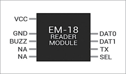
EM-18 RFID module (refer Fig. 3) is used to read the RFID tag. It decodes and transmits the signal to Arduino via a serial communication protocol.
LCD
A 16×2 LCD (liquid crystal display) displays the data received from Arduino board.
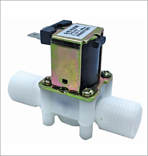
Solenoid. A 12V solenoid is used to control the flow of liquid. When the solenoid gets energised, it opens its valve and allows fluid to flow through the flow sensor; otherwise it stays closed and does not allow fluid to flow across it. The solenoid valve used in this project is shown in Fig. 4.
In this project, Arduino is the brain which controls the whole process. Analogue flow sensor connected to the Arduino board is shown in Fig. 5.
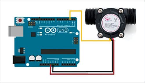
When liquid flows through the flow sensor, the liquid pushes against fins of the rotor, causing it to rotate. The shaft of the rotor is connected to a Hall effect sensor. It is an arrangement of a current flowing coil and a magnet connected to the shaft of the rotor, thus a voltage/pulse is induced as this rotor rotates. In this flow meter, for every litre of liquid passing through the sensor per minute, it outputs about 4.5 pulses.
Output pin of this flow sensor is connected to digital pin 2 of Arduino. When liquid flows, the output pulses are counted by the microcontroller in Arduino.
The total number of received pulses is converted into a specific unit like millilitre per second or litre per minute. This is due to the changing magnetic field caused by the magnet attached to the rotor shaft. Here, the flow rate in litres per minute (L/min.) is calculated using a simple conversion formula.
Pin Tx of EM-18 reader is connected to receive pin Rx of Arduino. When RFID tag swipes across EM-18 reader, it sends data to Arduino. If it matches with the programmed data, it sends a signal to the input of the relay driver consisting of transistor BC547 (T1). This input signal makes transistor to conduct, relay RL1 to get energised, which in turn connects 12V supply to solenoid via NO pin of relay and the solenoid gets energised. At the same time, “Place your pot/jug/cup” message is displayed on the first line of LCD1.
Energisation of solenoid allows the liquid to flow through the flow sensor. As the liquid starts to flow through the flow sensor, the amount of liquid being dispensed is displayed on the second line of LCD1.
When a predefined amount (programmed in the code) of liquid has passed through the flow sensor, the relay automatically gets de-energised and the flow of liquid stops. At the same time, “Remove your pot/jug/cup” message is displayed on the first line of LCD1.
If you want the same amount of liquid again, you just swipe the RFID card again across the RFID reader. You can repeat this again and again till the amount of liquid in the container finishes.
Software
The software code (liquid_vending.ino) is written in Arduino programming language. Arduino IDE is used for compiling and uploading the sketch to ATmega328 microcontroller of the Arduino board. Every RFID tag has a unique number. This number has to be included in the Arduino code/sketch.
Arduino code uses LiquidCrystal.h header file for the LCD and serial communication for reading the data from the RFID reader. Two built-in functions are used, namely, Serial.available( ) to return the RFID tag number arrived in the serial buffer and Serial.readString( ) to read a string of RFID tag numbers.
In this code/sketch, we used a variable as ‘int amount=1000’. This gives a default liquid amount of 1000 millilitres or one litre per card swipe. Just change the amount value as per your requirement.
Download Source Folder: click here
Construction and testing
- Connect all the components and modules as per the schematic diagram.
- Connect a 12V power supply from 12V adaptor or 12V battery to Vin pin of Arduino, relay driver and to relay NO pin.
- Connect relay common pin to the solenoid as shown in the circuit diagram.
- Check the default amount of liquid in the code for dispensing per minute.
- Swipe the RFID tag over EM-18 reader. If it matches the programmed RFID tag code, relay and solenoid will be energised, water from the source(tap) will flow through flow sensor.
- You will get all relevant information on LCD1 as already explained.
Make sure that there is sufficient amount of liquid in the source (water tap or container). Less amount of liquid in the source means less pressure in liquid flow in the pipe, resulting in inaccuracy in the liquid flow measurement.
Sagar Raj is founder and director of Shoolin Labs, Jaipur and Lifegraph Biomedical Instrumentation Pvt Ltd at Incubation Center, IIT Patna. He is guest faculty at NIELIT Patna
Mahendra Raisinghani is co-founder and director of Shoolin Labs, Jaipur and Lifegraph Biomedical Instrumentation Pvt Ltd at Incubation Center, IIT Patna


Innovative solution for rural and urban India.
Thank You for your feedback.
Excellent work. I tried this project and it worked properly. I thank the authors for lucid explanation and guidance
Thank You for your feedback.
Thank You for your feedback.
I am doing this project but 12v DC Sonenoid valve out flow of water is very low can you suggest any idea
Hi
Kumar Vimal
I hope you are good.
Please share your contact number or you can contact me +91-7992362007. So, I can discuss on this project. I need technical assistance from you.
Thank you
you can call on +91-8789926102