


In the modern busy world, the number of vehicles increases day by day and so the accidents too due to carelessness.
In that way, controlling the indicator On/Off plays a major role in avoiding such mistakes.
Creating an automatic vehicle indicator control with Arduino can significantly reduce accidents and save many lives. The goal of this project is to switch the indicator right/left bulbs by itself and the driver is all free from the stress.

Using a six-axis gyrometer cum accelerometer it is made possible to find the direction of movement of the four-wheeler’s steering wheel or a two-wheeler’s handlebar.
At a certain degree of movement from its origin towards the right, switches the right indicator and towards the left, switches the left indicator.

The hardware and software implementation including setting up the MPU6050 sensor and Arduino, and programming the system using Arduino IDE is explained in detail.
Fig 1 displays the Author’s prototype. Components used in the system are listed in the bill of materials table.
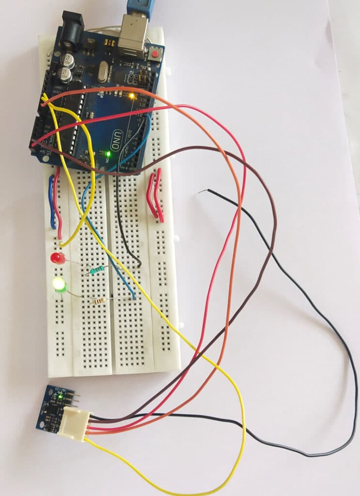
Fig. 1: automatic vehicle indicator control using Arduino
Bill of Materials:
| Components | Description |
| Breadboard | Microcontroller for programming |
| MPU6050(MOD2) | 6-axis gyro and accelero sensor |
| Micro USB | For programming |
| Breadbord | For circuit prototyping |
| Resistors – 330R | To power LED |
| LED | To indicate right/left in prototyping |
Circuit Diagram and Working:
The circuit diagram of the Vehicle’s right/left indicator automated control using MPU6050 and Arduino Uno is shown in Fig 2. It comprises Arduino Uno (MOD1), MPU6050 (MOD2), 330R resistors, LED and a few connectors.
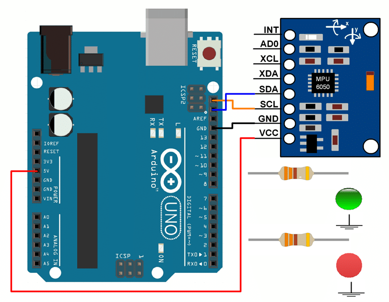
Fig 2: Circuit Diagram of Arduino and MPU6050 Connection
Arduino Code for Automatic Vehicle Indicator Control
For coding, use wire library (wire.h) is used for connecting and communicating with MPU6050 through I2C communication. The step-by-step coding explanation is given in the code snippet shown in Fig 3 and 4.
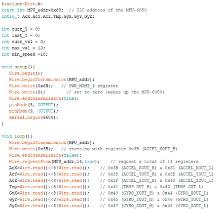
In the setup function, serial communication is initialized, and setup MPU6050 sensor and the pins used for LED as Output pins.
In the loop function,
- The accelerometer and gyrometer values are read in 3-axis
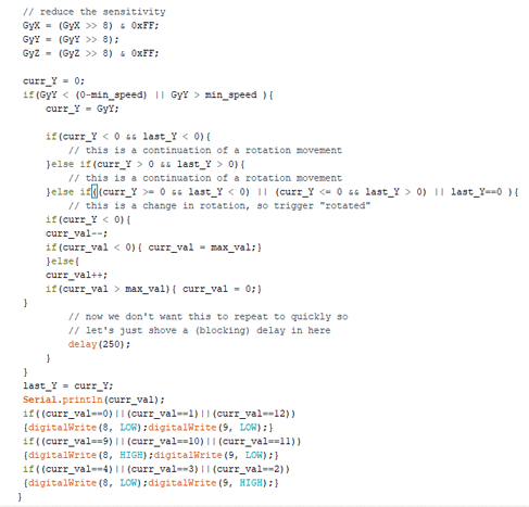
- Since it is all about rotation, we take GyY and process it further.
- Min speed is the least speed at which the rotation is to be considered and Max value is a division of 360 degrees. Here I have used 10 as min speed and 12 as maximum value for my prototyping.
- If the read value comes under the specified speed, then the value is moved to curr_y. The curr_y is saved in last_y before leaving the loop.
- Using the curr_y, the curr_val is determined.
- Based on the curr_val, it is found whether the four-wheeler’s steering wheel or a two-wheeler’s handle bar is moved in right or left and switches the corresponding LED.
Also Check: Top 30 Arduino Projects.
Construction and Testing:
Connect the sensor according to the circuit diagram shown in Fig 2, upload the code to the board, and power the device with a USB cable or 5V battery. Now make a change in the position of the prototype wheel. The corresponding LED lights up.
We have another vehicle-related project where you can detect a number plate using MATLAB; if interested, you can check that to by clicking on the link.
V. Shelvaraj is a Technical Director at TRY WIN TECH

