


 Described here is an easy-to-use circuit of an automatic infrared (IR) faucet controller suitable for hand hygiene and water conservation at homes, hospitals and offices. With this compact controller you can turn on and off a faucet automatically, preventing water wastage and saving energy costs.
The core part of the faucet controller is an electronic circuitry that determines the opening of the valve. An IR sensor continuously monitors objects like hands in front of the faucet. When you place your hand in front of the faucet, it automatically activates an electromagnetic relay to switch a solenoid valve, and concerted action provides enough water.
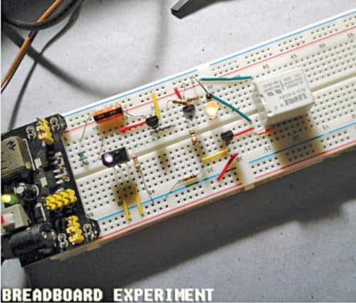
Another advantage of this battery-operated faucet controller is that, it can be installed on an existing water tap. The author’s prototype on a breadboard is shown in Fig. 1.

Circuit and working
The circuit diagram of the automatic IR faucet controller is shown in Fig. 2.
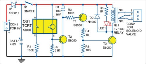
It is built around Schottky diode 1N5817 (D1), optical sensor (OS1), PNP transistor S8550 (T1), two NPN S8050 transistors (T2, T3), rectifier diode 1N4007 (D2), 5V-1CO relay, 6V solenoid valve and a few other components.

The circuit is constructed using a reflective optical sensor TCRT5000. It includes a 950nm IR emitter and phototransistor in a leaded package (with daylight blocking filter), which blocks visible light to a certain extent.
It is powered by 4.8V, drawn from a series of four nickel-metal-hydride (Ni-MH) rechargeable cells (1.2V each). External 6V DC power supply connected across connector CON1 is also provided as an alternate for running the circuit.
Power supply is protected by 1N5817 (D1). 6V can be used to recharge the battery pack, with only minor modifications. Switch S1 is used for turning the circuit on and off.
Resistor R1 controls the operating current of the IR inside TCRT5000 (OS1) within safe limits. R2 determines the detection sensitivity of the IR sensor. The IR emits an invisible constant beam of IR light. When a hand or object crosses this beam, some IR light is reflected back to the sensor.
This reflection is detected by the IR receiver (inbuilt phototransistor), which results in a voltage drop across R2. This switches off S8050 (T2). Next, S8550 (T1) and S8050 (T3) support efficient driving of the 5V electromagnetic relay (RL1) when a valid proximity detection is made.
The electromagnetic relay enables and disables the flow of water through the connected solenoid valve. The 10µF capacitor (C1) ensures a turn-off delay of about six seconds, so that the circuit does not stop water flow as soon as the proximity sensor is turned off.
LED1 works as active-state indicator. 1N4007 (D2) adds effective circuit protection, as it provides a path for the dissipation of stored energy (without flowing back) when RL1 is de-energised.
Construction and testing
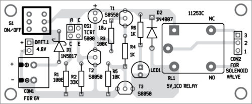
An PCB layout of the automatic IR faucet controller circuit is shown in Fig. 3 and its components layout in Fig. 4. After assembling the circuit on the PCB, connect 6V across CON1.
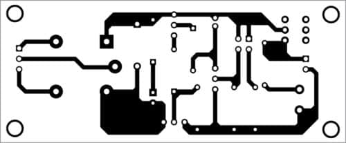
Download PCB and Component Layout PDFs: Click here
Build the circuit with the battery pack in a waterproof enclosure. Make sure that the IR sensor can easily detect hands near the washbasin.
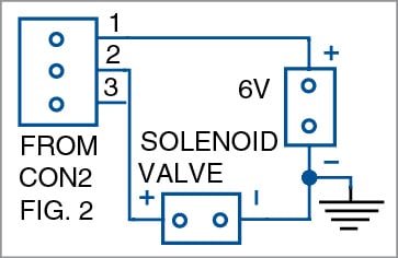
Note that, selection and installation of the solenoid valve depends on specific requirements. If you have a low-voltage (6V) solenoid valve, it may work with the 4.8V battery pack (most 6V types work smoothly with 4.8V). But if you have a high-voltage valve (greater than 6V), connect it to an external power supply. Wiring diagram of solenoid valve is shown in Fig. 6.
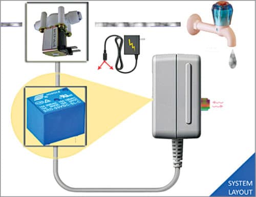
A proposed faucet arrangement of the system is shown in Fig. 5. The circuit draws under 50mA current in quiescent state. It goes above 100mA in active state if a low-voltage solenoid valve is also powered by the circuit.
T.K. Hareendran is founder and promoter of TechNode Protolabz

In this Automatic Infrared Faucet Controller, is the rechargeable battery used ? If No, what would be the battery life ?
With Regards
Any suitable 6V DC adaptor with 1 amp rating can be used for the circuit for testing. For backup, you can use four 1.2V nickel-metal-hydride (Ni-MH) rechargeable cells (to give total 4.8V).