 The storage compartment under the seat in scooters does not usually have a light, which makes it difficult to find small items in it at night. This circuit turns on a light automatically when the compartment is opened.
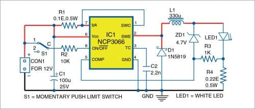
Circuit diagram of the light shown in Fig. 1 comprises NCP3066 monolithic constant-current switching regulator IC1, inductor L1, LED1 an LED that emits bright white light, Schottky barrier diode D1, micro lever limit switch S1, and a few other components. IC1 is configured as constant-current driver in buck topology to drive LED1. IC1, L1, D1, and current-sensing resistor R4 form a constant-current buck driver circuit. While capacitor C1 acts as a buffer, capacitor C2 determines operating frequency of the circuit. The 2.2nF capacitor C2 produces oscillating frequency of about 150kHz.

Limit switch S1 (see Fig. 2) should be fixed on the seat compartment’s wall in such a way that its switch lever remains pressed when the seat is in its normal position. This disconnects NC pin of switch S1 and no voltage is available at pin 8 of IC1, which keeps LED1 off.
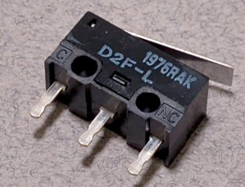
When the seat is opened, S1’s lever is released and disconnects NO pin and connects NC pin with Common. Thus pin 8 of IC1 gets positive supply, which enables it and LED1 glows. Zener diode ZD1 and resistor R3 protect the circuit from open circuit fault condition.

 Traditional buck topology requires an output capacitor on load end to filter the ripples. The capacitor is placed in parallel with LED1, or an array of LEDs, to lower the ripple current. IC NCP3066 controls the current through the load and not the voltage across it. Switching frequency of the IC is 100 to 250kHz, much higher than what a human eye can detect, so there is no ripple in the light. Since the IC is configured in continuous conduction buck mode with low p-p ripple, there is no need for an output filter capacitor.

IC NCP3066 has been used here instead of MC34063A DC-DC converter as it has following advantages:
MC34063A is designed for voltage conversion while NCP3066 is designed for current regulation.
- The frequency of operation of NCP3066 is up to 250kHz whereas it is limited to 100kHz in MC34063A.
- MC34063A does not have logic switching input pin whereas NCP3066 has logic-level shutdown capability.
- The feedback voltage of MC34063A is 1.25V whereas NCP3066 has low feedback of about 235mV.
- Constant-current regulation, cycle-by-cycle current limit, internal thermal shutdown with hysteresis, analogue and digital PWM dimming capabilities are additional advantages of IC NCP3066.
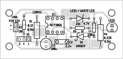
An actual-size PCB layout for the automatic light switch for scooter-storage compartment is shown in Fig. 3 and its component layout in Fig. 4. You may assemble the components on this PCB as per the component layout diagram or carefully on a general-purpose PCB. Keep the PCB in the seat compartment and fix switch S1 such that its lever remains pressed when the seat is in its normal horizontal position.
You may check the link for the datasheet and some other information here for easy and time-saving designs, and the worksheet file of NCP3066.
Download PCB and Component Layout PDFs: click here
A. Samiuddhin, a circuit designer, is B.Tech in electrical and electronics engineering. His interests include LED lighting, power electronics, microcontrollers, and Arduino programming