


 Wouldn’t it be amazing if our room light automatically adjusts its brightness according to our needs? Or if we can control the brightness of LED lights from our phone? This would not only make our life more comfortable, but it will also help us save a lot of energy.
All this can be made possible by using PID (Proportional Integral Derivative) controller. This controller has three steps for calculation Kp, Ki, Kd.
- Kp:- Here p stands for proportional and the output value is directly
proportional to the error value. If the error is high, the controlled output
is also high, and it deals with the present value of error. - Ki:- Here i stands for the integral control. It eliminates the error using
integration till it gets the desired value. - Kd:- Here d stands for derivative control. This d controller is responsible
to predict the future error based on current change over time.
The PID controller controls light brightness in the following steps.

- PID controller first reads the value from the light sensor
- Then it calculates the error from the present value of sensor to the
desired set point for brightness - After the calculation, the PID gives its output to LED and brightness to
meet the desired set point
What we are going to make?
In this project we are going to make an IOT Home automation system with PID
controller light. Our IOT system have the following features:
- App controlled light brightness
- RGB colour controller using app
- An adaptive brightness system
- Time based Automatic light/Fan controller.
Materials Required
- 1 RGB LED
- 1 LDR
- 110 OHM Resistor
- 1 Arduino UNO
- Bluetooth HC O5
- 1 Led
- Relay Module
Coding
We have installed the ‘PID_V1’ library to Arduino IDE. After this we can start
our coding.
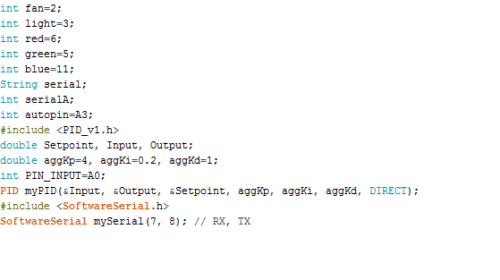
In the first part of our code, we will create a few variables to store the different
values required for our project. After that we will initialize the ‘PID_V1’ and
‘SoftwereSerial’ library to code (Refer Fig 1).
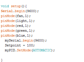
Next, we will create a setup function where we set the pinmodes for I/O pins
and the baudrate for Bluetooth HC 05. Here in this code, we have used
baudrate of 9600 but you can use different baudrate according to your
Bluetooth module setting. (Refer Fig 2).
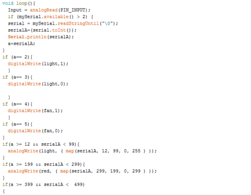
Next a loop function is created where we take the inputs from the app and
store in a variable named ‘serial’. After that several if conditions are created
for controlling the LED light brightness, fan and RGB led colour. After that we
will build a ‘while loop’ that checks the analog value to set the led light in
adaptive brightness mode. If this while loop reads the value less than 50 then it
goes in adaptive brightness.
App Making
In our project we have systems that control RGB light colour, room light
brightness, automatic and manual mode adaptive light as well as date and
time-controlled light. And we are going to give these features using an android
app.
Here we are going to use kodular app builder for making app (you can also use
MIT app inventor). In kodular app builder, we will create a layout for app and
add the following components to layout:
- 1 List picker
- 4 buttons
- 3 Text Boxes
- 2 Clock Timer
- 1 Bluetooth client
- 4 slider bar

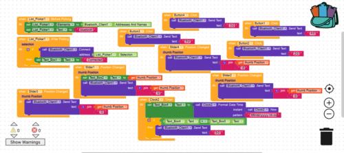
After creating the app layout and adding the above components, go to the
code blocks and join the code blocks as shown in Fig 5.
You can download the source code and app from the link below.
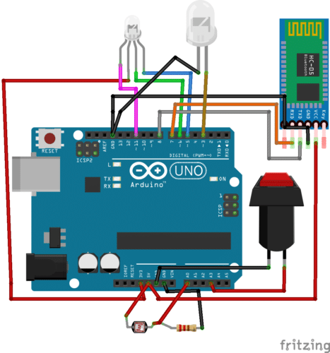
Connection
| Arduino UNO | Components |
| Pin 7 | Bluetooth TX |
| Pin 8 | Bluetooth Rx |
| GND | Bluetooth GND |
| 5V | Bluetooth VCC |
| 3V | RGB LED Common Cathode |
| Pin 5 | RGB Led R pin |
| Pin 6 | RGB Led G Pin |
| Pin 11 | RGB Led B pin |
| Pin 3 | LED Light |
| Pin A0 | Light Sensor LDR Pin |
| Pin A3 | Switch Pin |
Testing
First power the components and relay, then open the app we have created.
Now, test each feature of app one by one. First tap on connect button on app
and select the Bluetooth HC 05. After the successful connection you can
control the brightness of LED light of app by moving first slider bar. Move the
slider bar and set the brightness of light as per your need.
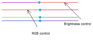
You can also turn lights off/on using the lights off /on buttons in the app. If you
want to change the RGB mood light colour, use the 3 rd , 4 th , 5 th slider bars to
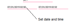
choose your desired colour. To make your room lights turn off automatically
while you are on a vacation or office, set the date and time in text box on the
left side. The app will automatically turn the lights off on the set time and date.
Now let’s test the main function of the project i.e. PID adaptive brightness
system. Turn on the auto button in the device. This will make the device go
into auto brightness mode and the LED will automatically change its brightness
according to the set value in PID controller code.
Note:- You can change the Kp, Ki, Kd values in code by hit and trial method to
get more accurate and best adaptive brightness.

Sharing of update it’s our biggest weapon , thank you
You can check our other DIY Project Also
very nice to get the knowledge…
Excellent post. I want to thank you for this informative read. I really appreciate sharing this great post. Keep up your work.
What type of LDR are you using?
The LDR having resistance 22K ohms in dark and 3K ohms. you can get it from kits and spare.
Everything is OK but I didn’t understand that why u didn’t use LDR and resistor in video you have uploaded but you have used it in circuit diagram.
Iam in a confusion whether to use them or not in my project. Plz help me.
Please can you tell where is the codes of Fig 3 and Fig 4 , they aren’t present on the website
Hi Kunal, the article is updated with the required images.
I like this post,And I guess that they having fun to read this post,they shall take a good site to make a information,thanks for sharing it to me.