


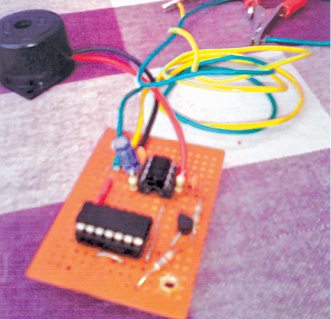
 Most power-resumption alarm devices produce non-stop alarm when power resumes. To overcome this problem, here is an automatic Power-Resumption alarm circuit that sounds an alarm for a few seconds only after power resumes. Author’s prototype is shown in Fig. 1.
Circuit and working
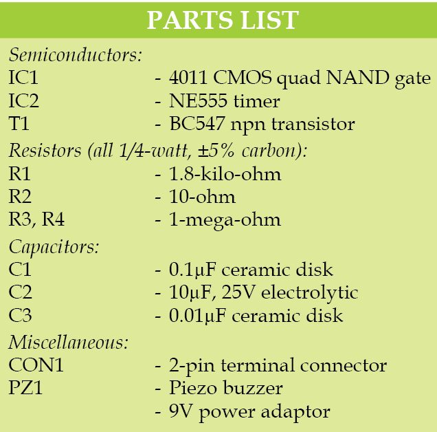
Fig. 2 shows the circuit diagram of the automatic power-resumption alarm. It is built around quad NAND gate CMOS IC 4011 (IC1), timer NE555 (IC2) and transistor BC547 (T1). IC 4011 has four NAND gates but in this circuit, we have used only two. A 9V power adaptor may be used for this circuit.
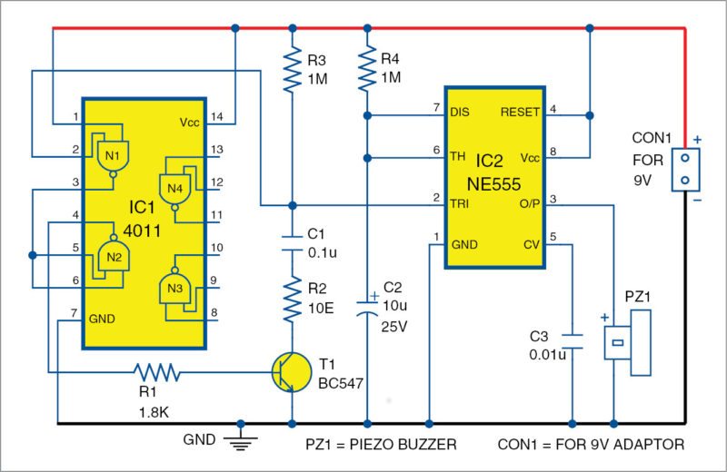

Whenever power failure occurs this circuit does not sound any alarm. But when power resumes it produces an alarm sound for about 11 seconds. This sound duration is determined by NE555 timer (IC2) configured in monostable mode. One-mega-ohm resistor (R4) and 10µF, 25V electrolytic capacitor (C2) are the timing components. Duration of the alarm can be increased or decreased by changing the values of R4 and/or C2. This is determined by the relationship:
T = 1.1×R4×C2 in seconds
Whenever power resumes, input pins 1 and 2 of NAND gate N1 become high, so NAND gate N2 output pin 4 also becomes high. This high output switches on transistor T1. IC2 receives a trigger pulse from T1 for a short time. Hence, the monostable circuit is switched on to produce an alarm.
Construction and testing

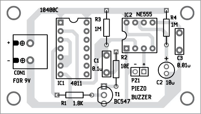
A single-side PCB pattern for the automatic power-resumption alarm is shown in Fig. 3 and its component layout in
Fig.4. After assembling the circuit on the PCB, enclose it in a suitable box.
This is an easy-to-assemble circuit. Its alarm sound can be increased by using an additional amplifier circuit.
Download PCB and component layout PDFs: click here
N. Pugalum Perumal holds a diploma in electrical and electronics. He is a design enthusiast.

Thanks
how to connect adapter to circuit?
instead of nand gate ic can i use a normal comparator?
Sure! You can use comparator as well, but you will need an extra components for it. Lets say you have comparator you will need ref. value in one of the inputs. Your ref value should be enought to trigger the timer 555. So you have 2 options:
1) resistive voltage devider
2) zener diode
I’ve printed the pcb and made the circuit, but it does not stop the alarm, I used bc546 instead of bc547, could this be the reason, please help me as I spend a lot of money till now on this circuit and I want it to work.
I’ve printed the pcb and made the circuit, but it does not stop the alarm, I used bc546 instead of bc547, could this be the reason?
tanq EFY i got output
You are most welcome.
AFTER FINISHING THE CIRCUIT CONNECTION HOW I CONNECT TO MAIN CIRCUIT?????
Can’t we get an image showing the circuit soldering
Is this project require software programmes if so what software we must use
sir can i use this this circuit with 12v
sir I need a pcb
Hi Ravikumar, the PCB is present at the end of the article.
Sir please can it serve as an ac
CAN I PLEASE GET THE PROTEUS PCB?
Sorry we do not use Proteus software. We use gEDA software instead