


The 555 timer IC is an integral part of electronics projects. Be it a simple project involving a single 8-bit microcontroller and some peripherals or a complex one involving system on chips (SoCs), a 555 timer is involved. These provide time delays, as an oscillator and as a flip-flop element, among other applications.
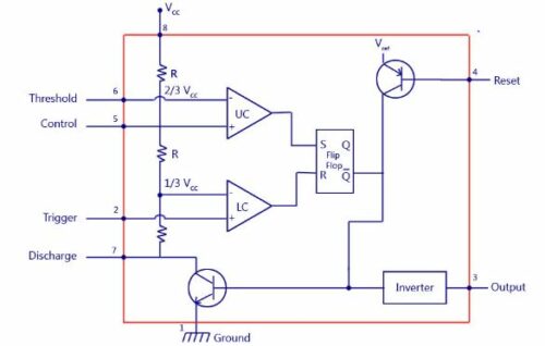
555 Timer IC Internal Circuit
Depending on the manufacturer, the standard 555 timer package includes 25 transistors, 2 diodes, and 15 resistors on a silicon chip installed in an 8-pin mini dual-in-line package (DIP-8). Variants consist of combining multiple chips on one board. However, 555 is still the most popular.

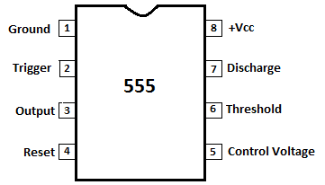
Let us look at the pin diagram to have an idea about the timer Integrated Circuit (IC) before we talk about the 555 timers working.
555 Time IC Pin Diagram

555 Timer Specification
555 timer is used in almost every electronic circuit today. A 555 timer works as a flip-flop or as a multivibrator; it has a particular set of configurations. Some of the major features of the 555 timers would be,
- It operates from a wide range of power, ranging from +5 Volts to +18 Volts supply voltage.
- Sinking or sourcing 200 mA of load current.
- The external components should be selected properly so that the timing intervals can be made into several minutes, along with the frequencies exceeding several hundred kilohertz.
- The output pin of a 555 timer can drive a transistor-transistor logic (TTL) due to its high current output.
- It has a temperature stability of 50 parts per million (ppm) per degree Celsius change in temperature which is equivalent to 0.005 %/ °C.
- The duty cycle of the timer is adjustable.
- Also, the maximum power dissipation per package is 600 mW, and its trigger pulse and reset inputs have logic compatibility.
555 Timer Working
The NE555 timer IC generally operates in 3 modes:
- Astable Mode
- Monostable Mode
- Bi-stable modes
Astable Mode
This means there will be no stable level of output. So the output will be swinging between high and low. This character of unstable output is used as a clock or square wave output for many applications.
Also Check: 555 Timer Calculator for Astable Circuit
Monostable Mode
This configuration consists of one stable and one unstable state. The stable state can be chosen as either high or low by the user. If the stable output is set at high (1), the output of the timer is high (1).
At the application of an interrupt, the timer output turns low (0). Since the low state is unstable, it goes to high (1) automatically after the interrupt passes. Similar is the case for a low stable monostable mode.
Bi-stable Mode
In bistable mode, both output states are stable. At each interrupt, the output changes from low (0) to high (1) and vice versa, and stays there. For example, if we have a high (1) output, it will go low(0) once it receives an interrupt and stays low (0) till the next interrupt changes the status.
More technical details can be found in the 555 Timer IC Datasheet.
People Also Ask
What supply voltage does the 555 timer require?
The standard bipolar NE555 works from 4.5V to 16V.
CMOS versions (LMC555/TLC555) operate from 2V to 18V with lower power consumption.
What is the typical output current capability of a 555 timer?
A bipolar 555 can source or sink up to 200 mA.
CMOS versions provide less (around 10–100 mA), depending on the model.
What determines the frequency of the 555 timer in astable mode?
The frequency depends on two resistors (R1, R2) and a capacitor (C). The charge-discharge cycle of the capacitor creates a square wave output. f = 1.44/(R1+2R2)C
Why do we use a capacitor on pin 5 (control voltage)?
Pin 5 sets the internal threshold reference voltage (normally 2/3 Vcc). Adding a 10 nF capacitor improves noise immunity and stabilizes operation. It can also be used to modulate the output frequency in VCO applications.
What is the purpose of the discharge pin (pin 7)?
Pin 7 connects to an internal transistor that discharges the timing capacitor during part of the cycle. This allows the 555 to control the timing intervals accurately.
How does the trigger pin (pin 2) work?
The trigger input starts the timing cycle when it falls below 1/3 Vcc. Even a short negative pulse can initiate timing, making it ideal for pulse generation.
Can a 555 timer generate PWM?
Yes. By adjusting the charge and discharge paths or using control voltage modulation, the 555 timer can generate pulse-width modulation signals.
What is the maximum frequency a 555 timer can generate?
A bipolar 555 can typically operate up to 100–500 kHz.
CMOS versions can exceed 2 MHz depending on the model.
What are some other timer ICs? Name them with their IC numbers.
Common timer ICs include IC 556 (dual 555 timer), IC 558 (quad timer), IC 74121 (monostable multivibrator), IC 74122 (retriggerable monostable) and IC 4047 (multivibrator/oscillator).
What is the function of pin 4 (Reset) of the 555 timer?
Pin 4 resets the timer when it is pulled LOW. Keeping it HIGH (usually tied to Vcc) allows normal operation.
How many transistors, diodes, and resistors are inside a 555 timer?
A standard 555 timer IC contains 25 transistors, 15 resistors, and 2 diodes.
What can a 555 timer in monostable mode be used for?
It generates a single fixed-width pulse, useful in timers, delay circuits, sensors, debounce circuits, and pulse shaping.
What is the function of the internal transistor in a 555 timer?
The internal NPN transistor discharges the timing capacitor through pin 7 when required, controlling the timing cycle.
What are the characteristics of a 555 timer multivibrator?
It can generate stable, adjustable pulse widths and frequencies with high reliability and minimal external components.
What is the function of the comparators in the 555 timer?
The two internal comparators compare the capacitor voltage with 1/3 Vcc and 2/3 Vcc thresholds to control the flip-flop that drives the output.
Which mode is used when a 555 timer has two resistors and one capacitor?
This configuration is the astable mode (oscillator).
What components determine the delay time in a 555 timer?
A variable resistor (potentiometer) and a capacitor determine the time delay.
Why is the 555 timer named “555”?
It is named after its internal three 5-kΩ resistors, which form a voltage divider.
How is the 555 timer used for switch debouncing?
In monostable mode, the 555 generates a clean single pulse when a button is pressed, eliminating noise and false triggers.
Why does my 555 circuit behave unpredictably or reset randomly?
Common reasons:
– Poor grounding
– Missing bypass capacitor across Vcc (use 0.1 µF)
– Noise on trigger/reset pins
– Incorrect capacitor polarity
– Using extremely high resistor values (>1 MΩ)
IC 555 Timer-based Projects
You can also check the more interesting 555 timer projects.
Check more such basic electronics articles.
This article was first published on 4th June 2017 and updated in November 2025.

It’s really very useful….
Thank you for your feedback.
Thanks. It’s great
Thanks for your feedback.
so deep explanation thanks for this.
You are most welcome.
This is usefull very engnneing students
Thank you for your valuable feedback.
Thanks…. It helped me a lot in my electronic project
Thank you for your feedback.
very good information to undestand about ic555..thank u..
You are most welcome.
Good information…. most useful
thank you for this information… itz really helping me for my project report…..
Clearly explained
Why it is named as 555
Because inside of IC it has 3 five kilo resistors so it is named as IC 555
Not true. ref: https://en.wikipedia.org/wiki/555_timer_IC#558_quad_timer.
It was very clear.. reason given for every step.. thanks a lot.. ?
You are most welcome.
Right Technical Information About 555 IC
Right Technical Information About 555 IC after testing and working with different circuits for several years
What about PWM. I use an arduino for that but the triple 5 could be much easier.
Thanks.Its really helpful…
You are most welcome.
It’s too nice
If the cct diagram of astable & monostable multivibrator were given,it may be much better
Thank you for your feedback.
thanks u v much….
You are most welcome.
THANKS FOR GIVING SUCH AWONDER FULL EXPLANATION
You are most welcome.
EFY was my regular accompaniment from 1974 to 1996 afterwards only special publications are viewed. It will be benificial for every generation. Thanks.
Very informative.Reading your articles on various topics leads to refresh the fundas.
thank you simple and useful article
You are most welcome.
Please mention the author of such documents so that we can follow their write ups
Hi Gireesh, this article is written by EFY Team.
if introduction to 556 also include with this , it will give good knoledge to beginners
i was making equal 3 sec stable out on and off pulse on astable mode and my positive peak was a small lengthier than negative peak. I tried a Lot but if i change the resistance and capacitor i will loose my either positive peak timing or negative peak timing and if i got it both as same then i will lose on and off time from 3 sec delay. but from your article i got idea about how monostable mode can help me. Now i am changing my path towards it. thanking you.
555 is my best friend since 1980s.
There is schematic error. Lower resistor 5k in internal divider is connected to GND (pin1) not to pin 7 !!!!
Thank you efy team
I m using this information for my project presentation
Its very heplful
You are most welcome.
Why it is named IC 555 ? why there is 555? My interview panelist asked me this question. Do anyone know?
Because it consist 3 voltage divider networks by 3 individual resistors that’s why it is named as ic555
you said that Ra and Rb are resistor right? what kind of resistor or what is the value of the resistor?
its really helpfull
can i know ur inst id?
You can send the email at [email protected]
What is the maximum frequency a 555 timer can produce?
The circuit diagram you posted is INCORRECT!!! You have mislabeled the pins going to both comparators and you have also incorrectly connected the comparator inputs to the voltage divider.
Hi Jeffrey, we are rechecking the content and images.
its really useful for my design and technology theory paper i really learnt alot thank you for this 🙂
You are most welcome.
The flip-flop used inside 555 is not connected to any clock, so is it a SR latch or a SR Flip-flop as flip-flop are connected with clock.