


 As the coronavirus pandemic continues, and could affect school-going children as well, the importance of smart devices has increased. This automatic school bell announces a recorded coronavirus alert after every school period. Due to its repetition several times a day, children are likely to imbibe the message and start practicing the hygiene as per the message. The system is simple and uses low-cost devices.
Circuit and working
Fig. 1 shows block diagram of the school bell that gives out a loud corona alert message. It comprises an Arduino Uno board, DS1307 real-time clock RTC module, TDA2030A 18W audio amplifier module, relay module, and speaker.

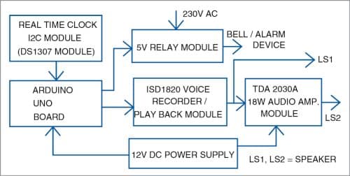
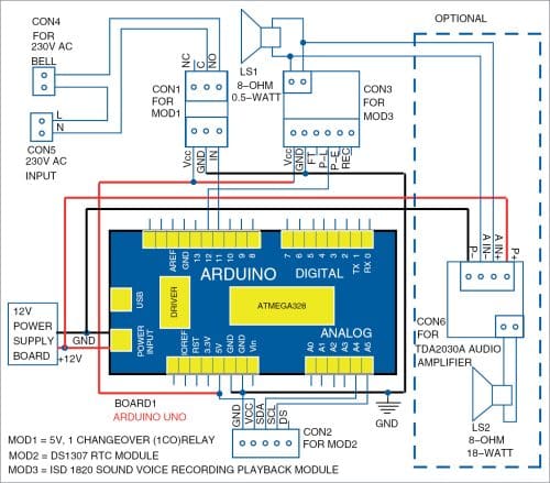
Fig. 2 shows circuit diagram of the school bell that works on 12V battery or adaptor. The project uses a voice recorder/playback module, which records the message and plays it back when triggered by the Arduino Uno board.
The voice record module shown in Fig. 3 is based on ISD1820 message record/playback device. It is a true single-chip voice recording device with a playback capability for 8 to 20 seconds. It has different modes of operation including REC, PLAYL, and PLAYE.

On pressing REC button RECLED glows. The button has to be kept pressed until the recording ends and then released.
PLAYL button gives out a level activated signal. When its input pin level transits from low to high, a playback cycle is initiated. This mode can be activated by the pushbutton switch on the board, or by the microcontroller through a high-level pulse. Playback continues until PLAYL is pulled low, or an end-of-message (EOM) marker is detected, or the end of the memory space is reached.
The recorded playback is initiated by pulse produced by Arduino microcontroller as per program through output pin 12 of the Arduino board. The output power of ISD1820 voice recorder/playback is about 0.5 watts.
PLAYE button gives out a playback edge-activated signal. When this button is pressed, a high-going transition signal is detected on this pin and the device starts the playback cycle. Playback continues until an EOM marker is encountered, or the end of memory space is reached.
Fig. 4. shows TDA2030A 18W audio amplifier module that amplifies the voice output of ISD1820 module. A 12V DC power supply is connected to this module and Arduino board.
It is a single-channel 18W power amplifier circuit designed around IC TDA2030A. The 10k adjustable resistance works as volume control. Speaker LS2 is connected at the output as shown.

The commonly used 220V AC school bell or buzzer can be connected to the relay’s normally-open (NO) pins. The 5V, single-changeover relay used for the purpose is shown in Fig. 5.

Another important module, which acts as an input to the microcontroller, is the DS1307 RTC module shown in Fig. 6. It keeps the clock running. The DS1307 serial real-time clock (RTC) is a low-power device with a 3V CR2032 lithium back-up battery. Its data (seconds, minutes, hours, day, date, month, and year information) is transferred serially to microcontroller through an I2C bidirectional bus. Apart from the power supply, only SDA (data line) and SCL (clock line) pins are required for establishing the I2C communication. The pin connections between I2C module and the Arduino board are shown in the circuit diagram.
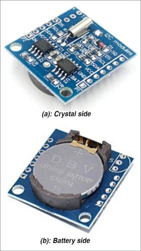
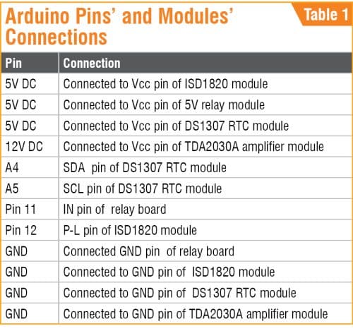
Table 1 shows the pin connections between Arduino Uno board and other modules in the project. Arduino Uno is a microcontroller board based on 8-bit ATmega328P microcontroller that is simple to use and interface. Mini breadboard can be used for power supply connections between the modules and Arduino Uno board.
Software
The circuit operates through software program schoolbell.ino loaded into the internal memory of Arduino Uno. The program implements all the necessary functionalities. It is simple and easy to understand. Comments are given at the end of each command line.
In this project the following two header files are necessary in the main code:
#include . The Wire library allows to communicate through I2C devices, also called 2wire or TWI (TwoWireInterface). The SDA (data line) and SCL (clock line) are used for communicating with DS1307 RTC module.
#include “RTClib.h”. Used For communicating with DS1307 RTC module.
In the next step, the code initialises the relay and ISD1820 module P-L pin as output. Then, Serial.begin(9600); command is used for serial communication for displaying the time on the serial monitor screen. It is mainly used for reference purpose.
In the loop, set the required timings for the alert message and the relay (buzzer) on and off timings. Two methods of setting the time in the RTC module are given below:
Method 1. rtc.adjust(DateTime(F (__DATE__), F(__TIME__))); line sets the time according to your computer time. It will set the present clock time of your system into the DS1307 I2C RTC module.
Method 2. rtc.adjust(DateTime (2021, 7, 21, 10, 0, 0)); command sets the time into the RTC module in the format: year, month, date, hours, minutes, seconds (such as 2021, July 21, 10:00:00 am). Once the time is set, the backup battery in the RTC module keeps the time running for a long time.
To ring the bell and give the alert message at a particular time, say, at 9 hrs, 30 mins, the command should be as given below:
if (now.hour() == 09 && now.minute() == 30 && now.second() <=15 )
The ‘if’ statement is used for comparing with the set time for hours and minutes. The ‘second() <=15’ is used to maintain the pulse high for a duration of 15 seconds to let the playback message to be completed. If you have a longer-duration playback message, change this time accordingly. In the ‘if’ loop, set the required timings for the alert message and the relay (buzzer) on and off timings.
After uploading the source code (schoolbell.ino) to Arduino Uno board, connect 12V DC power supply. The bell operates directly from 230V AC mains via the contacts of relay RL1 based on the scheduled programming time entered in the source code. You can feed multiple timings in the code as per the school-period timings.
Every time the bell rings, after five seconds, a preprogrammed recorded massage (say, Alert, please maintain proper distance) of about ten seconds is announced via loudspeaker LS1. For a louder message, the optional audio amplifier, shown within dotted lines in the circuit, can be used along with loudspeaker LS2.
Arduino Uno board is highly sensitive, so handle it carefully. Check the DC power supply jack’s input polarity (2.1mm centre-positive plug into the board’s power jack) before use.
Download Source Code
K. Murali Krishna works as junior engineer at BSNL, Rajahmundry, Andhra Pradesh. He is an electronics enthusiast, circuit designer, and technical writer.