


 A proven way to send an analogue signal a long distance is to transport the signal as a frequency using a voltage to frequency converter (VFC), a special circuit whose output is a frequency that is proportional to its input voltage.
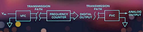
In principle, it is relatively easy to send a frequency signal over a long transmission path without interference through optical, coaxial, or radio links. The frequency is then reconverted to an analogue voltage by a FVC that is usually tailored to perform its inverse function, often using a phase-locked loop (PLL). Block diagram of the project is shown in Fig. 1.

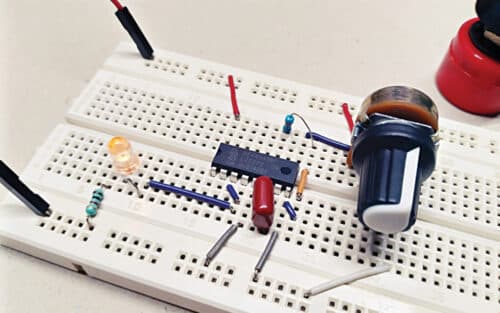
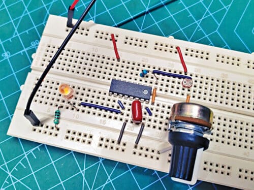
This project uses an odd approach to design and build a hobby-level VFC module using a handful of easily available and inexpensive electronic components. Author’s circuit of the VFC module wired on a breadboard is shown in Fig. 2.
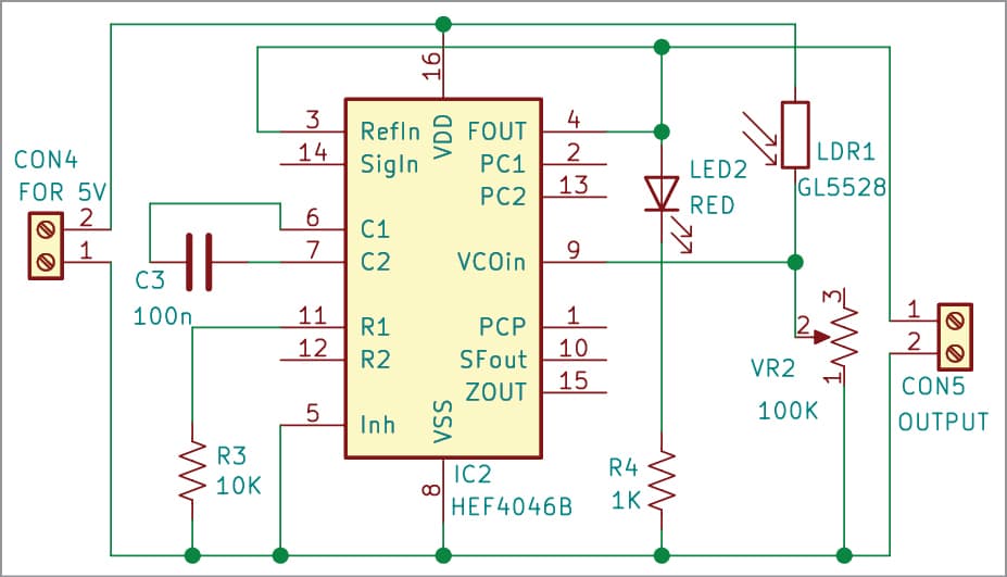
Schematic diagram of the VFC module is shown in Fig. 3. Please note, a well-regulated 5V DC power source is absolutely necessary to run this VFC circuit. Heart of the circuit is the venerable CMOS micropower phase-locked loop IC HEF4046B.
The HEF4046B (IC1) includes a VCO sub-system in addition to phase comparators and other elements. It can generate a square wave with 50% duty cycle. The frequency is reasonably close to 0Hz-1kHz range, which is curbed by the 100nF capacitor (C1) and the 10k resistor (R1).
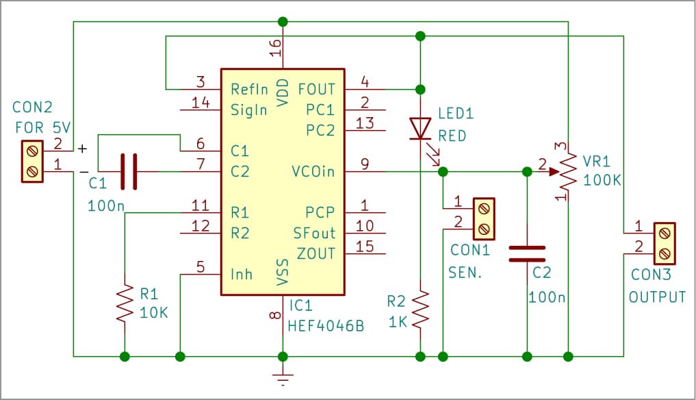
The output is available on pin 4 across CON3. The voltage input for the VCO on pin 9 (SEN) is connected across CON1. CON2 is used for connecting the 5V power supply.
As a quick aside, there’s an option to add an offset resistor between pin 12 and GND. The offset resistor has to be larger than the frequency-selection resistor R1, but otherwise can be infinite.
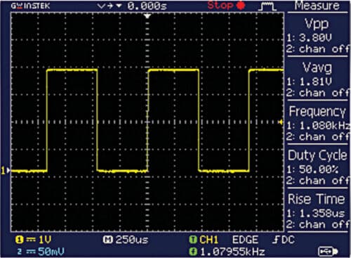
All we need next is a simple variable voltage source to test it. For that, the 100k linear potentiometer (VR1) can be hooked up, as shown in the schematic diagram. And then, VR1 can be used to vary the output frequency from around 0Hz to 1kHz at ease. Fig. 4 shows the frequency output at pin 4, which can be seen on an oscilloscope.
A few more key things worth noting are:
- VCO output across CON3 is the output point of the VFC module.
- CON1 is the 0-5V DC input connector of the VFC module.
- VR1 is an optional component, but it is helpful to test the VFC module. However, after construction and initial testing, it should be removed from the setup.
- LED1 (red/amber) is included deliberately to provide a visual indication of the output signal. The NXP datasheet does not include specific ratings for the VCO output, but seems to cater nothing greater than ~10mA. Since HEF4046B does not really appear to be tailored to drive any significant load, LED1 is also an optional component.
- Since the voltage input (at pin 9) of IC1 is very sensitive, if it’s not connected to anything, it might pick up power-line interferences and change the frequency wildly. Adding an appropriate capacitor (C2) can solve this problem, whether it’s useful or not depends on you.
Analogue sensor test using LDR (optional)
Now, let us do something that could not be done with a potentiometer as the frequency control element, that is, control the VCO frequency through an analogue sensor! To do that, follow the schematic diagram shown in Fig. 5, where a common GL5528 LDR (https://pi.gate.ac.uk/pages/airpi-files/PD0001.pdf) is connected to the voltage input of IC1 as the analogue sensor.
| Parts List | |
| Semiconductors: | |
| IC1 | – HEF4046B phase-locked loop IC |
| LED1 | – 5mm LED |
| Resistors (all 1/4-watt, ±5% carbon): | |
| R1 | – 10-kilo-ohm |
| R2 | – 1-kilo-ohm |
| VR1 | – 100-kilo-ohm potmeter |
| Capacitors: | |
| C1, C2 | – 100nF disc |
| Miscellaneous: | |
| CON1-CON3 | – 2-pin connector |
| – Breadboard | |
| Optional for Fig. 5 Circuit | |
| Semiconductors: | |
| IC2 | – HEF4046B phase-locked loop IC |
| LED2 | – 5mm LED |
| Resistors (all 1/4-watt, ±5% carbon): | |
| R3 | – 10-kilo-ohm |
| R4 | – 1-kilo-ohm |
| VR2 | – 100-kilo-ohm potmeter |
| Capacitors: | |
| C1, C2 | – 100nF disc |
| Miscellaneous: | |
| CON4-CON5 | – 2-pin connector |
| – Breadboard | |
| – LDR GL5528 | |
Here, the photoresistor (LDR1) and the potentiometer (VR2) combine to form a potential divider, so that the output frequency varies from 0Hz (completely dark) to 1kHz (strong light), depending on the intensity of the light falling on the photoresistor (see the oscillogram below). Another type of analogue sensor that can be used here is a thermistor; the frequency then will depend on the temperature.
Nevertheless, the analogue sensor setup is just about the same functionality as the potentiometer-tuned voltage controlled oscillator from before. However, VR2 does not play a crucial role at this time, so it may be substituted with a 100k fixed resistor. (It’s pretty easy if you know what you’re doing.) Fig. 6 shows the VFC module with LDR (optional) wired on a breadboard.
EFY note. This is just a design concept for a crude, hobby-level VFC module. In fact, a real VFC circuit is somewhat different than this. Keep in mind that VFC is a special type of VCO designed to be very linear over a wide range of input voltages, and it features many advantages and enhanced performance specifications, which a VCO doesn’t have. There are better designs out there, but they all probably demand dedicated ICs like AD654.
T.K. Hareendran is an electronics designer, hardware beta tester, technical author, and product reviewer
Innovative
Block diagram of the project is having a frequency counter and Frequency to Voltage converter. But nothing mentioned or explained in both text and video. Can I JUST use LM331 VCO instead of CD4046?