


A crucial component in many IoT and wearable electronic designs is the single-cell battery charging circuit. However, implementing this vital element and finding cost-effective design solutions can often be a concern.
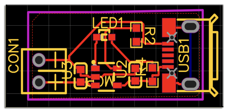
This guide presents a selection of circuits with PCB designs for single-cell battery charging, offering practical solutions for your IoT and device design projects.
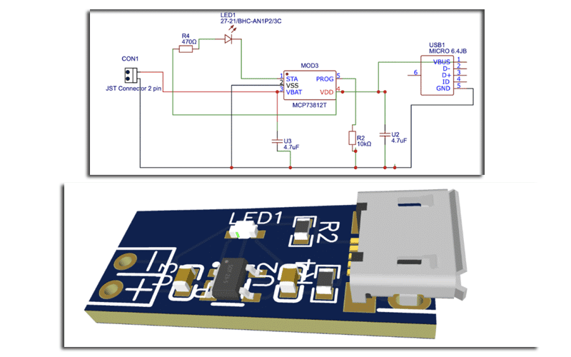
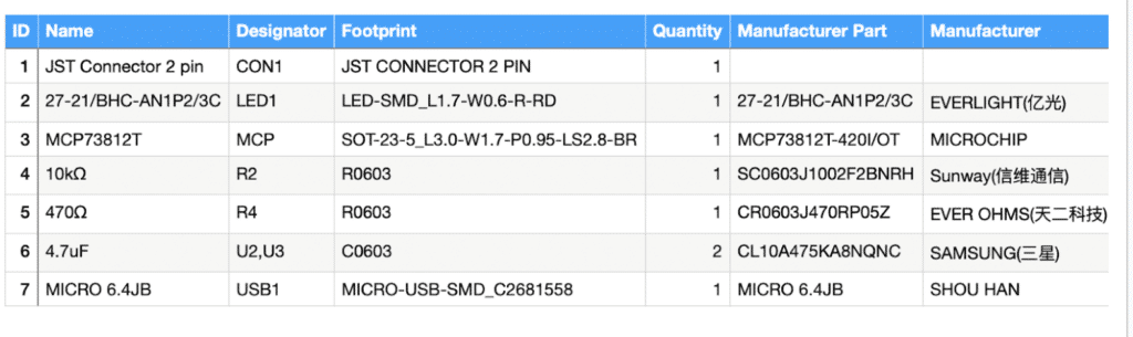
Battery Charging Circuit – Parts
To design this Single-Cell Battery Charging Circuit, below components are required:

Designing
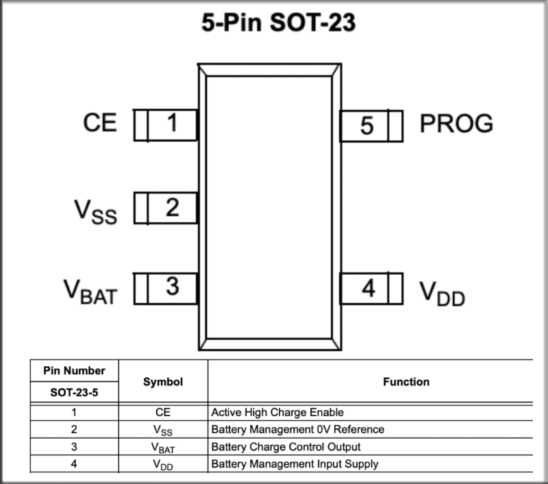
According to the datasheet of charging IC we have used has the following features-
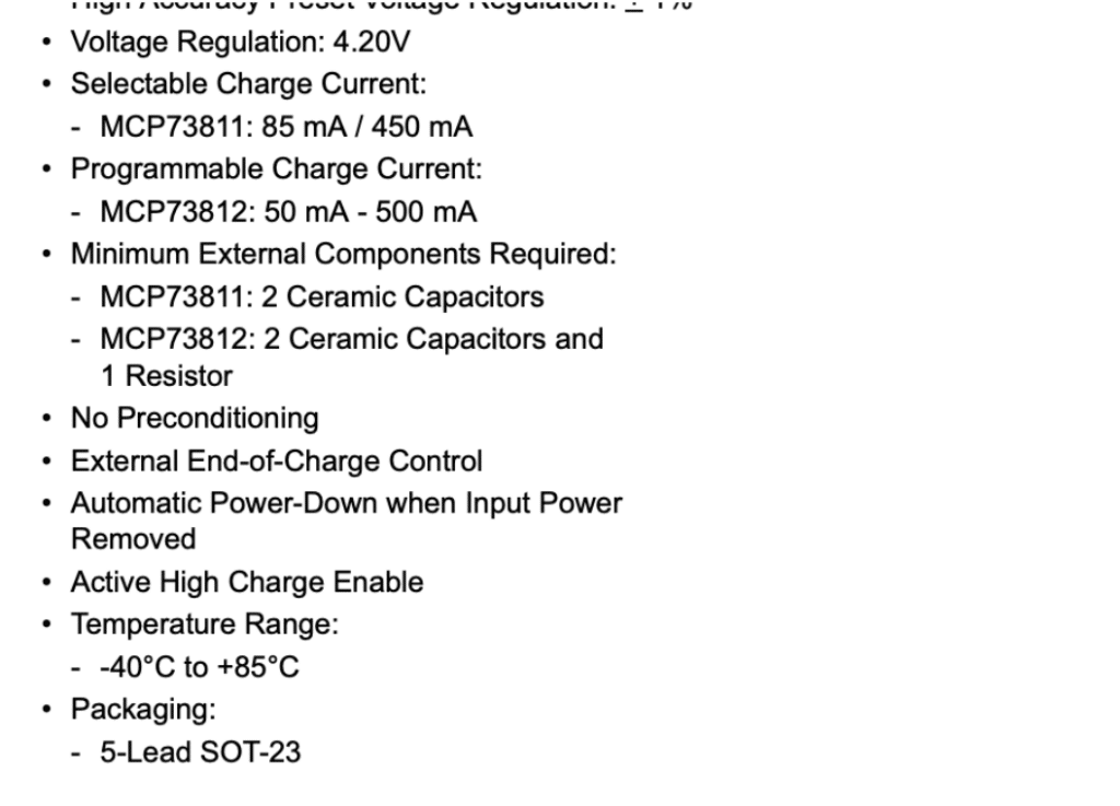
In this context, the circuit is designed to provide a regulated voltage output of 4.20V, ideal for charging 3.3V lithium batteries.
What sets it apart is its flexibility in offering selectable current outputs ranging from 85mA to 450mA. This current output can be easily configured using just 2 ceramic capacitors and 1 resistor.
Additionally, the circuit allows for the integration of an LED indicator, which can be customized to display the battery’s charging and discharging status according to your preferences.
It’s worth noting that the chip utilized in this circuit comes in two variations: the MCP73811 and MCP73812.
While both versions provide efficient charging solutions, they differ slightly in terms of the output current. The MCP73811 offers a charge current output of 450mA, whereas the MCP73812 delivers 500mA.
Moreover, you have the flexibility to control and program the output current using the Prog Pin, simply by incorporating a resistor.
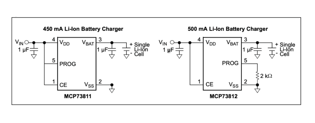
Programming the Current Output
As per the IC’s datasheet, you have the capability to program the charging current by manipulating the PROG pin and the corresponding resistor value connected to it.
This means you can precisely determine the current at which your battery will be charged.
Specifically:
- For the MCP73811, the PROG pin serves as a digital input selection. A logic Low setting corresponds to an 85 mA charge current, while a logic High setting results in a 450 mA charge current.
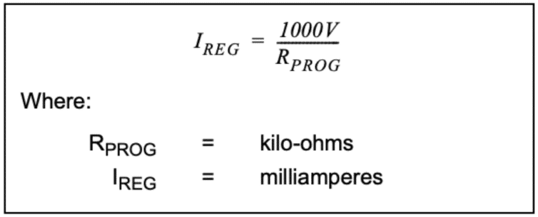
- In the case of the MCP73812, the charge current is established by connecting a resistor between PROG and VSS.
To calculate the resistor value required for your desired output current, refer to the formula in the datasheet. This flexibility allows you to fine-tune your charging circuit based on your needs.
If you have any doubt, feel free to ask in the comments below.
Also, check out more such interesting mini-projects.
Sir, Thank you for the useful project.
In the project description the IC number MCP73811 is mentioned in MCP7381 at least two instances.