LM317T and LM337T are well known and low cost adjustable voltage regulators with current limiting up to around 1.5A and power dissipation up to around 20W. It is useful to have bipolar power supply with LM317T and LM337T producing symmetrical output power supply. In that case LM317T will produce the positive output voltage and LM337T will produce the negative output voltage. The issue is how to adjust simultaneously both output voltages.
The usual solution is to build tracking voltage regulator with operational amplifier which track the positive or the negative output of the power supply. One of the issues in that case is that the power supplies and the other parameters of the op-amp can be a limiting factor for the required power supply. In order to avoid the limitations of most of the op-amps we will use stereo potentiometer to adjust simultaneously both output power supplies.
The good quality stereo potentiometers have differences between the two potentiometers in the couple less than +-5%. If that difference is too large we may use additional potentiometers to adjust the output voltages to be exactly the same or with the required difference. Here we will use that solution to produce two symmetrical power supplies. As additional advantage of the proposed solution we have both output voltages adjusted from almost ground level.
Description of the circuit
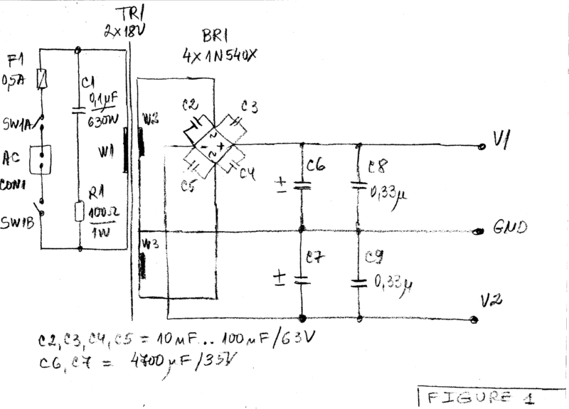
Figure 1 presents the unregulated section of the power supply.

The AC mains is applied to the connector CON1. The double switch SW1A+SW1B, the fuse F1, the resistor R1 and the capacitor C1 have protective functions and preferably should not be omitted. The transformer is selected according to the needed maximal output voltage and current. In that case it should be 2x18V to 2x20Vrms for more than 0.5Arms in order to produce output regulated voltage up to +-15V. The bridge rectifier BR1 should be for at least 1.5A/50V. It can be built from diodes 1N4001 or better, e.g. 1N540X are preferred.
The main filtering capacitors C6 and C7 should for at least 2200uF/35V and preferably 4700uF/35V. The positive unregulated voltage V1 and the negative unregulated voltage V2 are applied to the regulators shown on Figure 2. Figure 2 gives the regulated section of the power supply with LM317T and LM337T and with stereo potentiometer P1A+P1B for simultaneous adjustment of the output voltages.

The output voltage of LM317 normally starts from around 1.25V and the output voltage of LM337 normally starts from around -1.25V. Here D5 and D6 create positive reference voltage of around +1.3V which is used to create offset for IC2. Also D7 and D8 create negative reference voltage of around -1.3V which is used to create offset for IC1. That is why the output voltages V3 and V4 can start from almost ground levels. If we are in need of better stability we may use reference diodes for 1.2V as LM385-1.2 instead of the couples of ordinary diodes D5, D6, D7 and D8. The diodes D1, D2, D3 and D4 protect the regulators from reverse voltages.
Heat sinks
IC1 and IC2 should be mounted on appropriate heat sinks, e.g. with thermal resistance less than 4C/W. The maximal power dissipation can go up to 10W if we require output currents above 0.5A at lowest output voltages. When calculating the required heat sink we should take into consideration that the maximal power dissipation of LM317T and LM337T in case TO-220 is 20W, the thermal resistance junction-case is 4C/W and the maximal junction temperature is only +125C.
Testing
For the testing the power supply is connected to the mains (preferably with protective isolation transformer for the initial testing).
After that
- Outputs are loaded with resistors of 33 to 51Ohm with power dissipation at least 10W (preferably above 20W)
- The potentiometers P2 and P3 are put approximate in the middle position
- The output voltage is adjusted with the stereo potentiometer P1A+P1B approximate to the required voltages, e.g. to around +-10V.
- In case of need some readjustment of the output voltages is made with P2 and/or P3.
- Now if you connect and disconnect the loads the output voltages V2 and V4 should change slightly around the initial value of +-10V.
Conclusions
That short article presents bipolar adjustable power supply with LM317T and LM337T.
The power supply has three main features (particularities):
- The simultaneous adjustment of the output voltages is made with stereo potentiometer P1A+P1B.
- We have the possibility to adjust more precisely the output voltages with individual potentiometers
- Both output voltages can be adjusted from near ground level not from the typical +-1.25V.
These three features make this bipolar power supply useful for hobby and more professional usage.


