


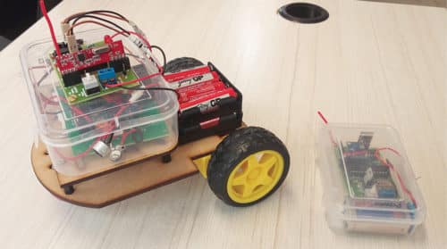
 This is a two-in-one project to control a robot in four directions (forwards, backwards, right and left) either by clapping or through simple gestures. It basically explains how a robot can be controlled using sound or gesture.
A switch is used to change mode of operation from sound to gesture control. You can make the robot to follow your yoga or dance moves, or react to various environmental sounds.
The robot control circuit has separate sections for clap and gesture. Both the sections have their own sensors. In clap section, an electret mic works as the sound sensor; in gesture mode, an accelerometer is used as the sensor.

Through the sound section you get clap-based switching control using a sound sensor, timer and decade counter. The gesture section uses a motion sensor like an accelerometer, Arduino-based ATmega328P microcontroller (MCU), radio frequency (RF)-based wireless control and encoder.
The entire robot is divided into two control sections: clap and gesture. Clap control section has only receiver while gesture control section has transmitter and receiver.
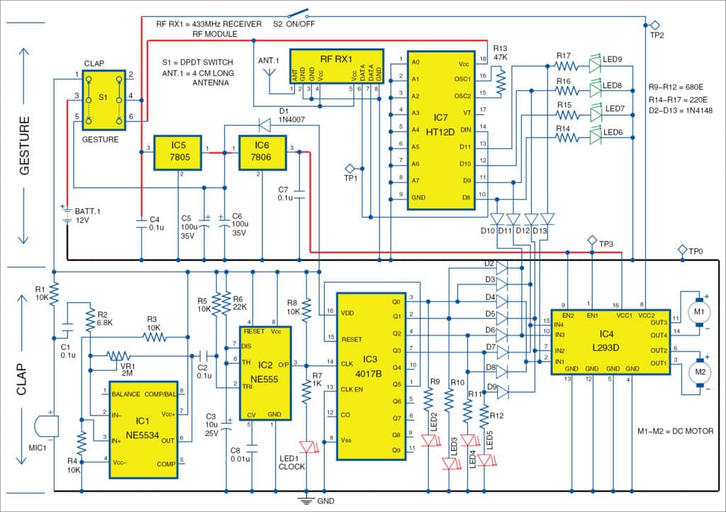
The circuit diagram of the clap- and gesture-controlled robot is shown in Fig. 1. For clarity, clap and gesture circuits are explained in separate sections.
Clap control
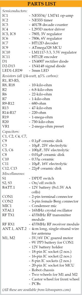
The clap control circuit is built around electret condenser microphone (MIC1), op-amp NE5534 (IC1), preset (VR1), timer NE555 (IC2), decade counter 4017B (IC3), L293D motor driver (IC4), two DC motors (M1 and M2) and a few other components.
Each clap sound works as a command signal to move the motor. The robot will move in different directions with four consecutive claps, namely, forwards, backwards, left and right, while the fifth clap stops the robot. VR1 preset is used to control sensitivity of the sensor, which, in turn, decides the range (distance) of control.
IC1 is used as the audio sound amplifier to amplify clapping sound received from the mic.
IC2 generates time delay and provides it to clock input of counter IC3. That is, output from pin 3 of IC2 goes to pin 14 of IC3, providing a clock pulse when you clap in front of the mic.
For the first clap, Q0 output of IC3 will be high, turning LED2 on. For the next clap, Q1 will be high, turning LED3 on. Simultaneously, Q0 will go low and LED2 will turn off.
Similarly, Q2 and Q3 will be high for the third and fourth claps, respectively. Clap sequence and LED status are shown in Table 1.
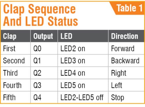
Output from IC3 also goes to motor driver IC4 via diodes D2 through D9 to move the robot. When Q0 is high, the motor moves in forward direction. When Q1 is high, it moves in backward direction. When Q2 is high, the motor moves in right direction, and when Q3 is high, it moves in left direction. The fifth clap resets IC3, and Q0 through Q3 outputs along with all corresponding LEDs switch off, and the robot stops.
For each clap, the respective LED (LED2 through LED5) glows to indicate direction of robot’s movement. Direction of motors can be changed by changing polarity of both the motors (M1 and M2).
Gesture control
The gesture control section consists of transmitter and receiver units.
Transmitter unit
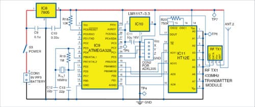
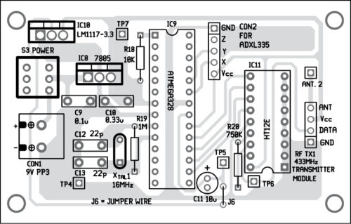
The circuit diagram of the gesture transmitter unit is shown in Fig. 2. It is built around Atmega328 MCU chip (IC9), ADXL335 accelerometer, 7805 voltage regulator (IC8), LM1117-3.3 voltage regulator (IC10), HT12E encoder (IC11), 433MHz RF transmitter module (RF TX1) and a few other components.
ADXL335 accelerometer
Normally, an accelerometer denotes positive x, y and z axes on the sensor package. These are defined so that linear acceleration aligned in the direction of these axes will give a positive accelerometer output. ADXL335 gives complete three-axis acceleration measurement within the range ±3g in x, y and z axes. Output signals of this module are analogue voltages that are proportional to acceleration.
 The transmitter along with ADXL335 sensor can be attached to your hand or palm. When you move your hand along with the sensor, the positional or gesture signal is processed by Atmega328 MCU and transmitted to the receiver unit through encoder IC11 and RF TX1 module. That is, by using different hand gestures, you can move the robot in different directions.
Arduino programming
Arduino programming tool is used to program ATmega328 MCU. The software program is written in Arduino programming language. You can program a fresh ATmega328 MCU with the help of Arduino IDE and Arduino Uno board.
First, load bootloader code into the MCU. For that, use Arduino Uno for in-system programming (ISP) given in the IDE, by selecting FileExamplesArduino ISP. Once the bootloader is uploaded into the MCU, gesture.ino code of this project can be uploaded.
Receiver unit
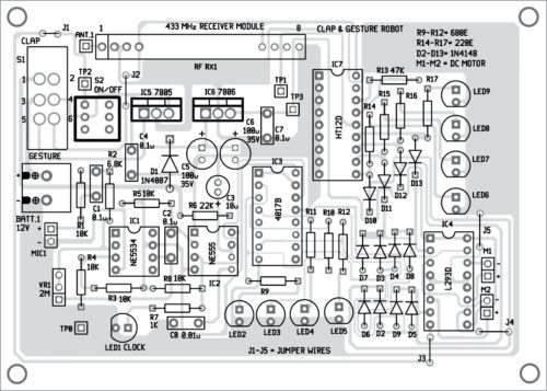
The receiver unit (shown in Fig. 1) is built around 433MHz receiver module RF RX1, HT12D decoder (IC7) and the motor driver section. DPDT switch (S1) is used for changing mode of operation from clap to gesture and vice versa.
ADXL335 sensor data transmitted through RF TX1 is received at the receiver unit through RF RX1. It goes to decoder HT12D and then to L293D motor driver section, including LED6 through LED9 and diodes D10 through D13. LEDs are used to indicate the signal status on various output pins of the decoder (IC7). Motor driver section is common for both modes (clap and gesture) for this project.
Switch S1 plays an important role here. With this double-pole double-throw (DPDT) switch, you can change mode of operation to clap or gesture control. When S1 is in clap mode, only clap section will be on and active. Similarly, when it is in gesture mode, only gesture circuit will be on and active. Switch S2 along with signal diodes (D2 through D13) are used to control the motors (M1 and M2).
Construction and testing
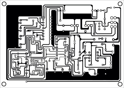
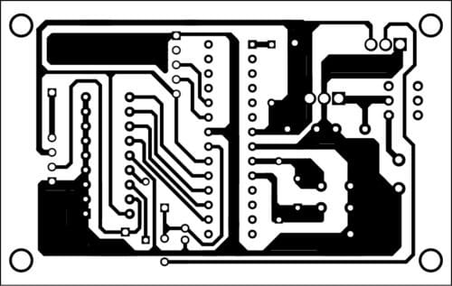
An actual-size PCB layout of the clap- and gesture-controlled robot is shown in Fig. 3 and its components layout in Fig. 4. PCB layout for the transmitter unit is shown in Fig. 5 and its components layout in Fig. 6. Assemble the components as per the circuit diagrams on the PCBs for gesture transmitter and robot control circuit, separately.
Download PCB and component layout PDFs: click here
After assembling, enclose the robot control section in a suitable box. Mount switches (S1 and S2) on the panel. Make sure that the antenna (ANT.1) and mic (MIC1) are exposed by providing suitable holes for them on the box. Connect 12V battery (BATT.1) and motors (M1 and M2), and place BATT.1 on the chassis of the robot.
Enclose the transmitter section also in a suitable box. Make a small hole each for the antenna (ANT.2) and on/off switch (S3) on the panel. A 9V PP3 battery may be used as power supply for the transmitter unit. Connect the 9V battery to CON1.
For testing, keep S1 in clap mode and switch on S2. Clap in front of the mic. Using a screwdriver, gently turn the wiper of preset VR1 left or right to change sensitivity as per requirement. On each clap, the robot will move in a particular direction, and on the fifth clap it will stop. Status of each clap is indicated by the respective LED (LED2 through LED5).
Keep S1 in gesture mode, and switch on S2 and S3.
Hold the transmitter unit in your hand and slowly move your hand in different directions. The robot should move in the direction of your hand. If robot moves in any other direction, check and interchange the motor connections.
For gesture control, position of the accelerometer sensor in the transmitter unit plays an important role. Calibration of sensor can be done by moving the transmitter in different directions and seeing how the robot moves. Each movement is indicated by the glowing of LEDs (LED6 through LED9).
For fun, you can conceal the gesture transmitter in the pocket of your shirt or pants. With slight adjustments in ADXL 335 sensor’s position and motor connections, you can make the robot follow you. That is, as you move around along with the transmitter unit, the robot will follow you. You can fool your friends and make them think that the robot follows you without any control. If the transmitter unit is in your shirt pocket, you can make yoga moves and the robot will follow your moves, too. These are just a few interesting things for demonstration, but this project can be extended to other areas and applications, too.
Download Source Folder
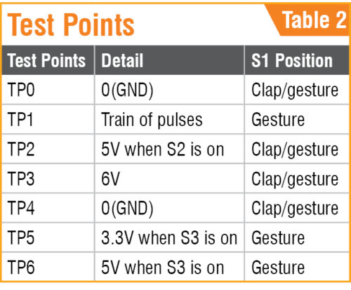
For troubleshooting, check voltages at various points listed in Table 2. Also check for dry soldering, proper connections, heating of ICs, battery voltages and polarities of motors.
Sani Theo is a technology enthusiast and technical editor at EFY
How I can get ready to use control PCB robot
Let me provide the information of ready control board for projects
You may get complete kit of this project from Kits’N’Spares. Please contact them on [email protected]