


 Presented here is an electronic toy circuit for your child’s entertainment. The concept of a joint family is disappearing, and childcare is also becoming difficult. It is best to spend some quality time with your child by doing things that interest him/her, or by putting things together to have some fun. This circuit has both audio and visual aspects for entertainment. There is nothing better than seeing a huge smile spread across a child’s face.
The Circuit diagram of the electronic toy for a child is shown in Fig. 1. It is built around binary counter (IC1), ten different colour LEDs (LED1 through LED10), three buzzers (PZ1 through PZ3) and a few other components.

IC CD4060 has an internal oscillator and a fourteen-stage binary divider to provide a delay without using a high-value resistor and capacitor. Resistor R1, preset VR1 and capacitor C1 form the clock circuitry. Switch S1 is used to provide 9V power supply to the circuit. Pin 12 of IC1 is connected to ground enabling the inbuilt oscillator of IC1.

When the circuit is powered on and VR1 is at 1-mega ohm, then O4 output of IC1 goes high every five seconds to light up LED1 and LED2. Output pin O5 of IC1 goes high every ten seconds to activate buzzer PZ1 through switch S2. Output pin O6 of IC1 goes high every twenty seconds to activate LED3 and LED4, while output O7 of IC1 goes high every forty seconds to activate PZ2 through switch S3.
Similarly, output O8 of IC1 goes high every eighty seconds to activate LED5 and LED6. Output O9 of IC1 goes high every 160 seconds to activate PZ3 through switch S4. Output O10 of IC1 goes high every 320 seconds to activate LED7 and LED8. Output O12 (not used here) of IC1 goes high every 1280 seconds. Output O13 of IC1 goes high every 2560 seconds to activate LED9 and LED10.

You can vary output timings (O4 through O13) of IC1 by varying VR1. Outputs can also be varied by changing the values of R1 and C1. Resistors R7, R8 and R9 limit the tone produced from the buzzers. The circuit works with a 9V battery.
Construction and testing
Working of the circuit is simple. When power is turned on by closing switch S1, LED1 through LED10 blink and attract the attention of the child. When the child starts playing with this gadget by varying VR1, blinking rates of the LEDs change along with a buzzing sound. Piezo buzzers are optional.
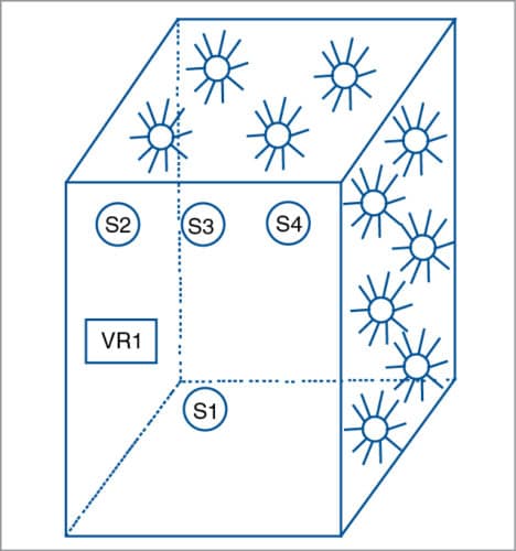
Assemble the circuit on a breadboard or Veroboard. Enclose it in a waterproof plastic box with holes for mounting the LEDs on the panel, as shown in Fig. 2. Fix VR1 and switches (S1 through S4) on the front panel. Keep the piezo buzzers and 9V battery inside the box.
Riddheesh Dwivedi is an electronics hobbyist

Nice
Can u plz send me some easy mini projects
You can get all mini-projects here.