


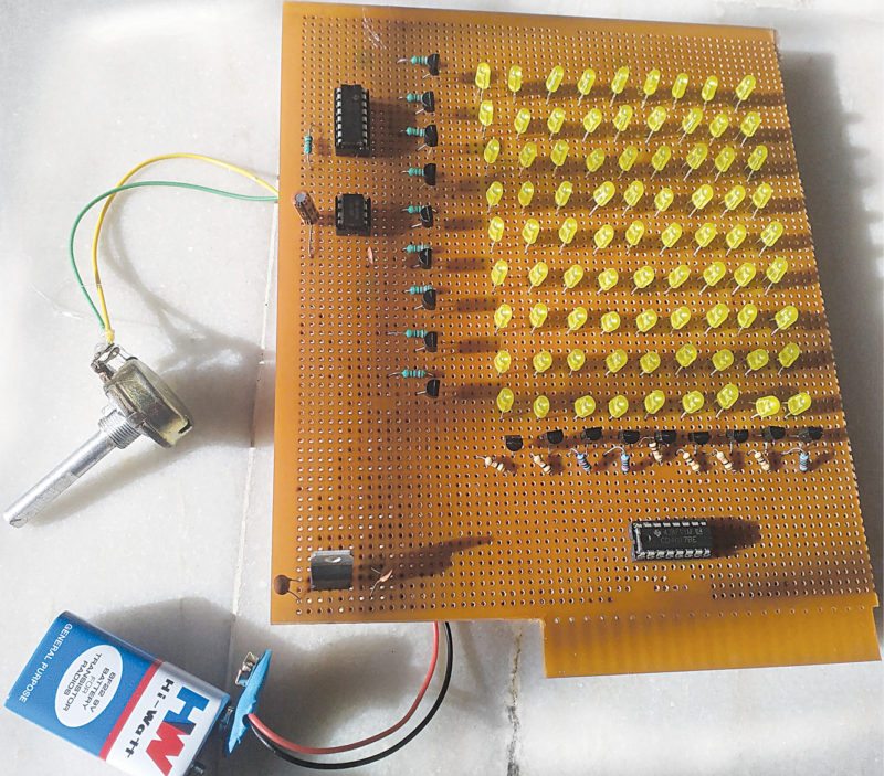
This is a simple CD4017 based LED light using NE555 timer for clock generation. We have used only two CD4017 ICs to construct the project in 9×9 matrix format. The circuit is useful for applications like running light systems in halls, decorations, dance programmes, counting and so on. Fig. 1 shows the author’s prototype.
Circuit and working
Circuit diagram of the CD4017 based LED light is shown in Fig. 2. It has two CD4017 decade counters (IC3 and IC4) and an NE555 timer (IC2). The 9V battery power supply is stepped down to 5V using a 7805 voltage regulator along with two 0.1µF capacitors (C3 and C4) to eliminate any ripples in supply voltage.
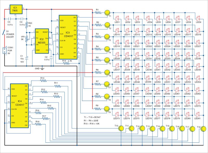
IC2 is wired in astable multivibrator mode. For clock frequency generation, 10µF capacitor (C1), resistor R20 and potmeter VR1 are used. VR1 is used to change the LEDs’ flashing rate. Frequency (f) can be calculated using the relationship:

f=1/(0.69(R20+2×VR1)×C1)
IC2 generates clock for the first decade counter (IC3). This counter controls the rows (anodes of LEDs) with the help of nine BC547 transistors (T1 through T9). These transistors can be controlled by output pins (O0 through O9) of IC3 along with 220-ohm resistors (R1 through R9) that are connected to collectors of T1 through T9 for current-limiting purpose.
Tenth output (O9) is fed to pin 14 (CLK) of CD4017 (IC4) as clock input. Columns of the LEDs can be controlled through collectors of BC547 transistors (T10 through T18) that are connected to cathodes of LED columns. Outputs of IC4 are connected to bases of transistors T10 through T18 through resistors R10 through R18, respectively.
Clock rate can be varied with the help of 5-kilo-ohm potmeter (VR1) to produce stunning running lights effect based on the concept of persistence of vision.
Construction and testing
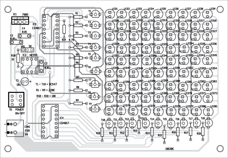
Double-side PCB layouts for the 81-LED chaser light are shown in Figs 3 and 4, respectively, and their component layouts in Fig. 5. After assembling the circuit on the PCB, enclose it in a suitable plastic box.
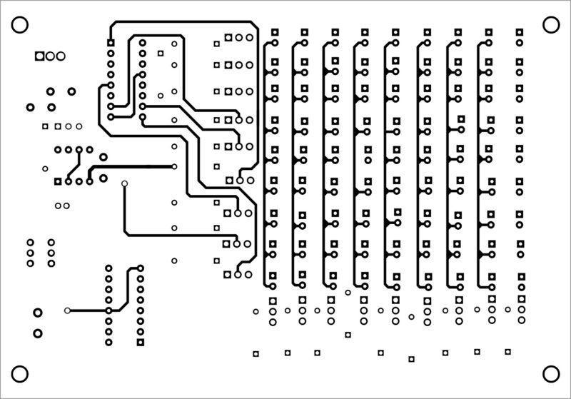
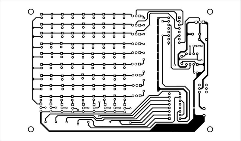
Download PCB and component layout PDFs: click here
The circuit works off a 9V battery.
Pamarthi Kanakaraja is assistant professor in Usha Rama College of Engineering and Technology, Andhra Pradesh
Is the order in which the LED’s light up reflected in their designators? That is to say, does LED1 light up first, followed by LED2… all the way down to LED81?
Thanks
dear sir
part list send
What software is used for creating the PCB Layout?
Is the schematic drawn in the same applicationas as the PCB design?
I need Electronic Kits for hobby
You can check out Kits N Spares website: https://www.kitsnspares.com/