


Here we discussed the step-by-step guide to building Cellphone Operated Land Rover Without Microcontroller.
Mobile robots have the capability to move around in their environment and are not fixed to one physical location. Mobile robots can be “autonomous” which means they are capable of navigating an uncontrolled environment without the need for physical or electro-mechanical guidance devices.
Alternatively, mobile robots can rely on guidance devices that allow them to travel a pre-defined navigation route in a relatively controlled space.

In contrast, industrial robots are usually more-or-less stationary, consisting of a jointed arm and gripper assembly, attached to a fixed surface.
Controlling a robot wirelessly is possible with several methods such as Remote, Bluetooth, Wi-Fi, etc. But, the controls of these communication methods are limited to certain areas, and complicated to design as well. To overcome these difficulties, we have come up with a Mobile Controlled Robot.
A Mobile Controlled Robot is a mobile device, which provides a wide range of wireless control abilities to your robot unless your cell phone gets out of signal.
Cost of the Project: ₹ 967/-
List of Components
| No. | Components | Quantity | Technical Specification |
| 1 | Robot Chassis | 1 | |
| 2 | DC Motor (100 RPM) | 2 | 12V DC Motor |
| 3 | PCB | 1 | |
| 4 | IC L293D | 1 | Motor Driver IC |
| 5 | IC CM8870 | 1 | DTMF Decoder IC |
| 6 | Resistor | 3 | 1K, 100K, 300K |
| 7 | Battery | 1 | 12V & 9V |
| 8 | Plastic Wheels | 2 | |
| 9 | Crystal | 1 | 3.58 MHz |
| 10 | Universal Headphone Jack | 1 | |
| 11 | Capacitors | 2 | 0.1uF |
| 12 | Capacitors | 2 | 10uF |
| 13 | LED | 1 | |
| 14 | Wires |
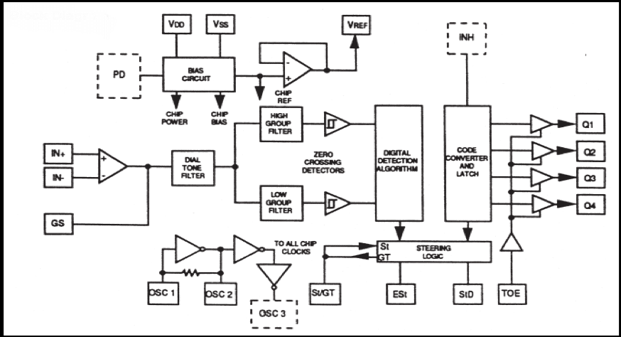
Integrated Circuits
(a) IC CM8870
The CAMD CM8870/70C provides full DTMF receiver capability by integrating both the band split filter and digital decoder functions into a single 18-pin DIP, SOIC, or 20-pin PLCC package. The CM8870/70C is manufactured using state-of-the-art CMOS process technology for low power consumption (35mW, max.) and precise data handling. The _lter section uses a switched capacitor technique for both high and low group _lters and dial tone rejection.
The CM8870/70C decoder uses digital counting techniques for the detection and decoding of all 16 DTMF tone pairs into a 4-bit code. This DTMF receiver minimizes external component count by providing an on-chip di_erential input amplifier, a clock generator, and a latched three-state interface bus. The on-chip clock generator requires only a low-cost TV crystal or ceramic resonator as an external component.
CM8870 can also be termed as a DTMF receiver and it is integrated with both band split filter and decoder function into a single IC 18-pin. The power consumption of the IC is 35mW maximum.
BAND SPLIT FILTER: A single tone is superimposed with two frequencies, one is low and the other is high frequency, to split these two frequencies into high group frequency and low group frequency, and then it is decoded.
DECODING: In CM8870, digital counting techniques are used to decode all 16 DTMF tone pairs into a 4-bit code.
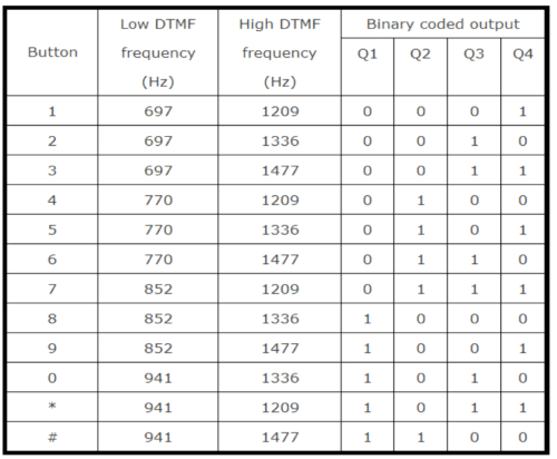
For example: If you press key 3, the corresponding low and high frequency is 697Hz and 1477Hz (refer to the DTMF frequency table) these two frequencies are superimposed to produce a single tone, and this tone code is sent through the microphone and the signal is received by a DTMF receiver (CM8870), then the superimposed frequencies are separated by a bandpass filter, then decoded using digital counting techniques and the digital output is 1100 (Q1, Q2, Q3, Q4) pin (11, 12, 13, 14). So it is very simple to interface.
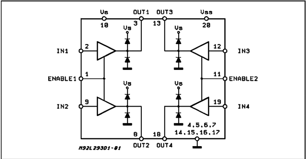
(b) IC L293D
L293D is a dual H-bridge motor driver integrated circuit (IC). Motor drivers act as current amplifiers since they take a low-current control signal and provide a higher-current signal. This higher current signal is used to drive the motors. L293D contains two inbuilt H-bridge driver circuits. In its common mode of operation, two DC motors can be driven simultaneously, both in forward and reverse directions.
The motor operation of two motors can be controlled by input logic at pin 2, pin 7, and pin 10, pin 15. Input logic 00 or 11 will stop the corresponding motor. Logic 01 and 10 will rotate it in clockwise and anticlockwise directions, respectively.
Enable pins 1 and 9 (corresponding to the two motors) must be high for the motors to start operating. When an enable input is high, the associated driver gets enabled. As a result, the outputs become active and work in phase with their inputs. Similarly, when the enable input is low, that driver is disabled, and their outputs are off and in the high-impedance state.
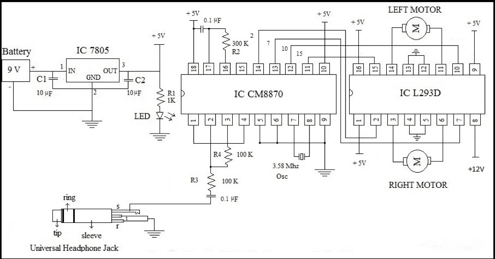
Cellphone Operated Land Rover Circuit Diagram
Cellphone Operated Land Rover Working
The Model works as follows:
DTMF-based robotic vehicle circuit consists of DTMF decoder IC, driver IC L293D IC and motors.
The tone from the DTMF encoder is given to the DTMF decoder IC. The decoder IC internally consists of an operational amplifier whose output is given to pre-filters to separate low and high frequencies. Then it is passed to the code detector circuit and it decodes the incoming tone into 4bits of binary data. This data at the output is directly given to the driver IC to drive the two motors. These motors rotate according to the decoded output.
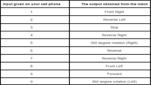
If the button pressed from mobile is `1′, it gives a decoded output of `0001′. Thus motor connected to the first two pins will get 0 volts and the second motor will have 5 volts to one pin and 0 volts to another pin. Thus the second motor starts rotating and the first motor is o_. So, the robot moves in one direction either to the left or right. If the robot is to rotate forward or backward then the binary value should be either `0101′ or `1010′.These values indicate that two motors rotate in the same direction i.e. either forward or backward. The following table gives the low frequency, high frequency and binary output value of each button pressed on the keypad.
Output Table
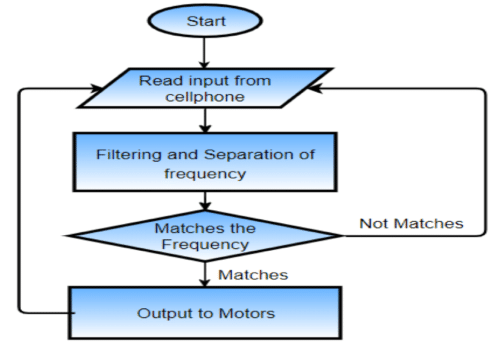
Flowchart
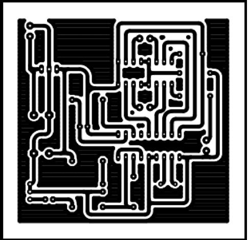
PCB Layout
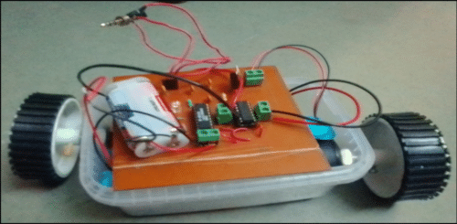
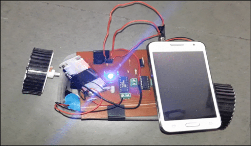
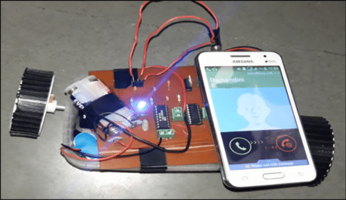
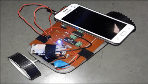
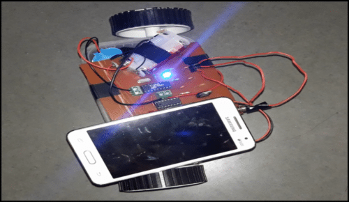
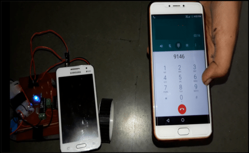
Output Photographs

Cellphone Operated Land Rover Applications
• It can be used in the military for disposing of landmines.
• Best suited for Search and rescue operations.
• Addition of a wireless camera helps to access this robot from any part of the world to monitor your house or office.
• DTMF robots with slight modifications can be used in industrial applications.
• DTMF robot with human detector sensor can be used at the time of disasters like earthquakes to detect the human under buildings.
• DTMF robot with a camera can be used in surveillance systems.
Difference between the Old Project and this Project
| Sr. No | The published project | Our proposed project |
| 1 | Microcontroller ATMega16 is used, which is of costs around 328/- on the Amazon website as of date 4th January 2019 | We are not using any microcontroller so, there is zero cost for the microcontroller. |
| 2 | Programming is needed to program the microcontroller | No programming. Ease of operation |
| 3 | More components were used namely, IC ATmega16, IC MT8870, IC L293D, and IC 74LS04. Many other components like diodes, etc are used. In total, 25 components are needed. | Our project needs only IC CM8870 and IC L293D. In total, we have 13 components only, which makes the circuit smaller and easy to implement. |
| 4 | The approximate cost of the project is around 1500/- to 1600/-. | The cost of our project is 800/- to 900/-, which is much less comparatively. |
| 5 | ATmega16 (as per datasheet) – Power Consumption @ 1 MHz, 3V, and 25°C for ATmega16L Active: 1.1 mA |
IC CM8870 (as per datasheet): less than 35mW |
very good design
Any Mobile App need here?
What simulation software is used?