

This proposed system aims to address the shortcomings of the existing system by utilizing cutting-edge technology to reduce road accidents caused by over-speeding and drunk driving. The system consists of an RF module, an MQ3 alcohol sensor, and a microcontroller to measure the vehicle’s speed and the driver’s blood alcohol content. The data collected is then processed, and if the driver is found to be under the influence of alcohol, the system prevents ignition, and if the vehicle is found to be over-speeding, the speed is automatically controlled to comply with the posted speed limit.
Components Required
1. RF Module: The RF module is used to wirelessly transmit data between the vehicle and the control center. It is capable of sending and receiving data over a distance of up to 100 meters.
2. MQ3 Alcohol Sensor: The MQ3 sensor is used to measure the driver’s blood alcohol content. It is a gas sensor that detects ethanol, the primary component of alcoholic beverages.

3. Microcontroller: The Atmega 328 microcontroller is used to control the system’s overall functionality. It processes the data collected by the RF module and the MQ3 sensor and uses it to control the vehicle’s speed and prevent ignition if necessary.
Working
The proposed system works by first measuring the vehicle’s speed using the RF module. This data is then compared to the posted speed limit, and if the vehicle is found to be over-speeding, the system automatically controls the speed to comply with the limit.

Simultaneously, the MQ3 sensor measures the driver’s blood alcohol content. If the level is above the legal limit, the system prevents ignition, and the vehicle cannot be started until the driver’s alcohol level drops below the legal limit.
If the driver’s alcohol level is below the legal limit, the system allows ignition, and the vehicle can be started. However, if the driver’s alcohol level exceeds the legal limit while driving, the system will alert the driver and automatically control the speed to prevent accidents.
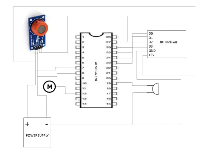
Connection Diagram
Coding
#include <LiquidCrystal.h> #define trigger 8
#define echo 7
#define motor 6
#define buzzer 13
#define bm2 10
#define rf0 A0
#define rf1 A1
#define rf2 A2
#define rf3 A3
#define al A4
LiquidCrystal lcd(12, 11, 2, 3, 4, 5); float time = 0, distance = 0; int reading;
int speed=0;
int temp = 0;
void setup()
{
lcd.begin(16, 2);
pinMode(trigger, OUTPUT); pinMode(echo, INPUT);
pinMode(buzzer, OUTPUT); pinMode(bm2, OUTPUT);
pinMode(rf0, INPUT);
pinMode(rf1, INPUT);
pinMode(rf2, INPUT);
pinMode(rf3, INPUT);
pinMode(al, INPUT);
lcd.print("SPEED COTROL AT"); lcd.setCursor(0, 1);
lcd.print("SENSITIVE ZONES"); delay(3000);
reading = digitalRead(al);
if (reading==LOW)
{
digitalWrite(buzzer,1);
analogWrite(motor,0);
lcd.clear();
lcd.print("ALCOHOL DETECTED"); lcd.setCursor(0, 1);
lcd.print("VEHICLE STOPPED"); delay(1000);
while(digitalRead(al) == 0){} }
}
void loop()
{
digitalWrite(rf0, HIGH);
digitalWrite(rf1, HIGH);
digitalWrite(rf2, HIGH);
digitalWrite(rf3, HIGH);
lcd.clear();
lcd.print("SPEED COTROL AT"); lcd.setCursor(0, 1);
lcd.print("SENSITIVE ZONES"); delay(200);
digitalWrite(bm2, LOW);
digitalWrite(buzzer, LOW);
delayMicroseconds(2);
digitalWrite(motor,1);
temp = 0;
reading = digitalRead(rf0);
if (reading==LOW)
{
 speed=150;//
digitalWrite(buzzer,1);
analogWrite(motor,speed);//
lcd.clear();
lcd.print("SCHOOL ZONE");
lcd.setCursor(0, 1);
lcd.print("60KM SPEED PLEASE"); delay(1000);
while(digitalRead(rf0) == 0){} }
analogWrite(motor,speed);//
reading = digitalRead(rf1);
if (reading==LOW)
{
 speed=120;
digitalWrite(buzzer,1);
analogWrite(motor,speed);
lcd.clear();
lcd.print("HAIR PIN BEND"); lcd.setCursor(0, 1);
lcd.print("30KMS SPEED");
delay(1000);
while(digitalRead(rf1) == 0){}//changed }
analogWrite(motor,speed);
reading = digitalRead(rf2);
if (reading==LOW)
{
 speed=75;
digitalWrite(buzzer,1);
analogWrite(motor,speed);
lcd.clear();
lcd.print("OVER BRIDGE");
lcd.setCursor(0, 1);
lcd.print("10KMS SPEED");
delay(1000);
while(digitalRead(rf2) == 0){}
}
analogWrite(motor,speed);
reading = digitalRead(rf3);
if (reading==LOW)
{
digitalWrite(buzzer,1);
analogWrite(motor,0);
lcd.clear();
lcd.print("Danger");
lcd.setCursor(0, 1);
lcd.print("ZONE DETECTED");
delay(1000);
while(digitalRead(rf3) == 0){}
}
reading = digitalRead(al);
if (reading==LOW)
{
digitalWrite(buzzer,1);
analogWrite(motor,75);
lcd.clear();
lcd.print("ALCOHOL DETECTED");
lcd.setCursor(0, 1);
lcd.print("SPEED REDUCED..");
delay(1000);
while(digitalRead(al) == 0){}
}
}
This code uses an Arduino board connected to several sensors and actuators. The board is connected to a LiquidCrystal display and an ultrasonic sensor with a trigger and echo pin, as well as a buzzer, a motor, and multiple input sensors including four pins of RF modules (rf0-rf3) and an alcohol sensor (al). The code uses these sensors to control the speed of the motor based on the readings from the proximity sensors, display messages on the LCD, and detect alcohol in the environment.
Conclusion
The proposed system offers a reliable and effective way to reduce road accidents caused by over-speeding and drunk driving. By utilizing advanced technology, the system can accurately measure the vehicle’s speed and the driver’s blood alcohol content and automatically control the speed to comply with the posted speed limit and prevent ignition if necessary. This system has the potential to make a significant impact on road safety and save countless lives, and we hope that it will be implemented on a wider scale in the future.